


Abstract
Aims
Cementless acetabular components rely on press-fit fixation for initial stability. In certain cases, initial stability is more difficult to obtain (such as during revision). No current study evaluates how a surgeon’s impaction technique (mallet mass, mallet velocity, and number of strikes) may affect component fixation. This study seeks to answer the following research questions: 1) how does impaction technique affect a) bone strain generation and deterioration (and hence implant stability) and b) seating in different density bones?; and 2) can an impaction technique be recommended to minimize risk of implant loosening while ensuring seating of the acetabular component?
Methods
A custom drop tower was used to simulate surgical strikes seating acetabular components into synthetic bone. Strike velocity and drop mass were varied. Synthetic bone strain was measured using strain gauges and stability was assessed via push-out tests. Polar gap was measured using optical trackers.
Results
A phenomenon of strain deterioration was identified if an excessive number of strikes was used to seat a component. This effect was most pronounced in low-density bone at high strike velocities. Polar gap was reduced with increasing strike mass and velocity.
Conclusion
A high mallet mass with low strike velocity resulted in satisfactory implant stability and polar gap, while minimizing the risk of losing stability due to over-striking. Extreme caution not to over-strike must be exercised when using high velocity strikes in low-density bone for any mallet mass.
Cite this article: Bone Joint Res 2020;9(7):386–393.
Article focus
-
This in vitro study investigated the effect of impaction technique (including mallet mass, mallet velocity, and number of strikes) upon acetabular component stability.
Key messages
-
This study identified a trend of stability deterioration with excessive impaction strikes.
-
The use of a high mass mallet with low strike velocity may allow adequate fixation in low-density bone while minimizing the possibility of stability deterioration.
Strengths and limitations
-
The effects of each element of impaction technique (mallet mass, strike velocity, and number of strikes) upon clinically relevant outcomes have been reported. To our knowledge, no comparable study has been published.
-
This study used a synthetic bone model. The magnitudes of the effects reported may vary in live bone tissue. In addition, only time-zero effects can be reported.
Introduction
The majority of hip implants used in total hip arthroplasty (THA) in Europe, Australia, and the USA are now cementless1-4 and show reduced mortality risk compared to cemented implants.5,6 Cementless procedures have been shown to have favourable outcomes even in revision cases, despite decreased bone stock, and are often recommended over cemented alternatives.7-9 Cementless implants rely on a mechanical press-fit to achieve initial stability. If successful, this can result in lifelong secure implant fixation.10
Press-fit stability is achieved by impacting an implant into an undersized cavity in the bone and generating hoop strain, creating friction at the implant/bone interface. With adequate strain the implant is stable and long-term bone ingrowth is promoted.11,12 However, if there is too little strain the implant may be unstable, and small movements can occur during loading, preventing bony ingrowth.13,14 Implant stability is particularly important during revision cases, where bone stock and quality may be poorer. In these cases secure implant stability is more difficult to achieve,9,15 and the likelihood of fracture may increase.16,17 Early instability and loosening has been reported as the main cause of cementless implant failure following revision.7,18,19 In order to maximize the benefits of using cementless implants, particularly in more difficult cases, stability must be achieved.20
Much previous research has focused on how initial stability is influenced by implant/bony factors: component design,21,22 implant surface,23 component stiffness,24 bone density,25 and bone/component interference.26-30 However there is a paucity of literature discussing surgical technique in seating cementless implants. Impaction technique (mallet mass, mallet velocity, and number of impaction strikes) played a crucial role in seating over 34,000 cementless components in the UK in 2017. Previous work has investigated the role of impaction energy or implantation force, both of which depend upon mallet mass and velocity, implant stability, and seating.31 However the effect of number of impaction strikes remains unclear. As it can be difficult for the surgeon to accurately infer when a component is seated,32 the effect of under- or over-impacting an acetabular component requires investigation.
This study uses an in vitro model to answer two questions: 1) how does impaction technique affect a) bone strain generation and deterioration (and hence implant stability) and b) seating in different density bones?; and 2) can an impaction technique be recommended to minimize risk of implant loosening while ensuring seating of the acetabular component?
Methods
Setup
An in vitro drop tower was used to impact acetabular components into synthetic bone (Figure 1). By varying the height of the drop, the rig is able to mimic surgical mallet impaction strikes in a repeatable manner. In addition the drop rig mimics in vivo soft tissue boundary conditions. Briefly, the synthetic bone is mounted to a mass/spring/dashpot that provides the same displacement and acceleration rate under impact as the human acetabulum during surgery. This ensures the same damping of soft tissue seen in vivo is represented in vitro. The details of the test setup and human cadaver validation have been described previously.31,33
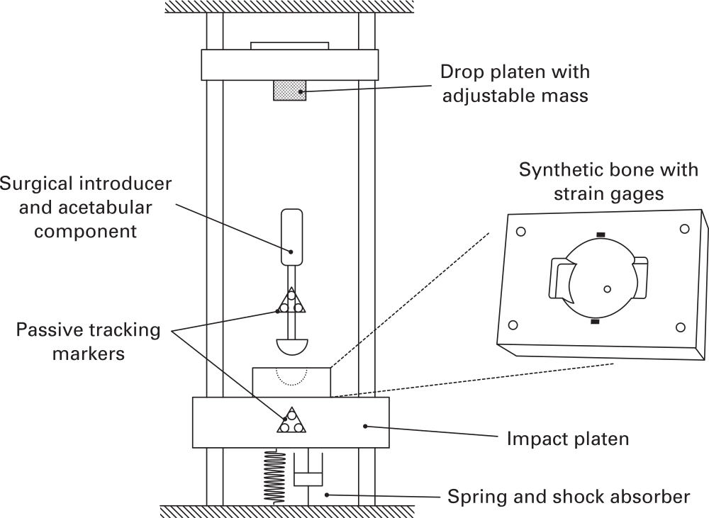
Fig. 1
Experimental impact setup.
Expanded polyurethane foam (Model #1522 to 02 and #1522 to 04; Sawbones, Pacific Laboratories, Malmö, Sweden) was used as a repeatable synthetic bone substitute for the acetabulum: the high-density (30 PCF) foam replicated good-quality bone with a strong cortical rim while the low-density (15 PCF) foam replicated poorer quality bone, such as the exposed cancellous, sub-chondral bone seen in revision cases.34-38 The bones were computer numerical control (CNC) milled to create a 53 mm diameter acetabular cavity, with a previously validated anatomically representative geometry, including two ‘notches’. These were used to simulate the pinching effect of the ischeal and ilial columns, applying similar forces to acetabular components as in vivo testing.39-42 The hemisphere cavity was centred 1 mm below the surface of the block.
The acetabular components used were designed to have a rim-to-rim stiffness similar to commercially available devices,1,43 manufactured with a 3 mm shell thickness in Ti6Al4V alloy. Each component was manufactured with an extruded spigot, projected into the component from the pole, allowing components to be attached to a straight introducer for impaction. A finite element analysis was used to ensure the resulting components fell within the range of stiffness reported for commercial acetabular components.38,43 A rough outer surface (Rz > 500 μm) was applied to the components, representing a typical implant fixation surface.44 Then, 55 mm and 54 mm component sizes were chosen for the 15 PCF and 30 PCF models resulting in 2 mm and 1 mm diametric interference respectively, which represents typical clinical practice.11,27,45,46
Testing
Data were acquired for three strike velocities and three strike masses. Low, medium, and high velocities of 1.5 m/s, 2.75 m/s, and 4.0 m/s respectively were chosen based upon existing literature and previous testing.33,47-49 A video demonstration intended to aid surgeon replication of these velocities is available in the supplementary material (Supplementary Video i). Low, medium, and high strike masses of 0.6 kg, 1.2 kg, and 1.8 kg were implemented by changing the mass of the drop platen (Figure 1) and were chosen to cover a range of commonly used surgical mallets. Five repeats were completed for each of the nine mass/velocity combinations, in each of the two densities of synthetic bone. Strain and displacement data were recorded for ten strikes for each setup. In total 180 tests were completed.
Implant stability: strain measurement
Strain gauges (350 ohm, SGT-3F/350TY11; Omega, Manchester, UK) were used to measure hoop strain on the surface of the bone. Two gauges per bone were glued radially around the cavity periphery, 2 mm from the cavity edge (Figure 2). This location has previously been shown to experience the highest strain.21,31 Strain gauge data were acquired for one second following each strike using a USB datalogger (NI9327; National Instruments, Budapest, Hungary) in quarter bridge configuration. Raw data were captured using Labview (National Instruments, 2014) and analyzed using MATLAB (Mathworks, Natick, Massachusetts, USA).
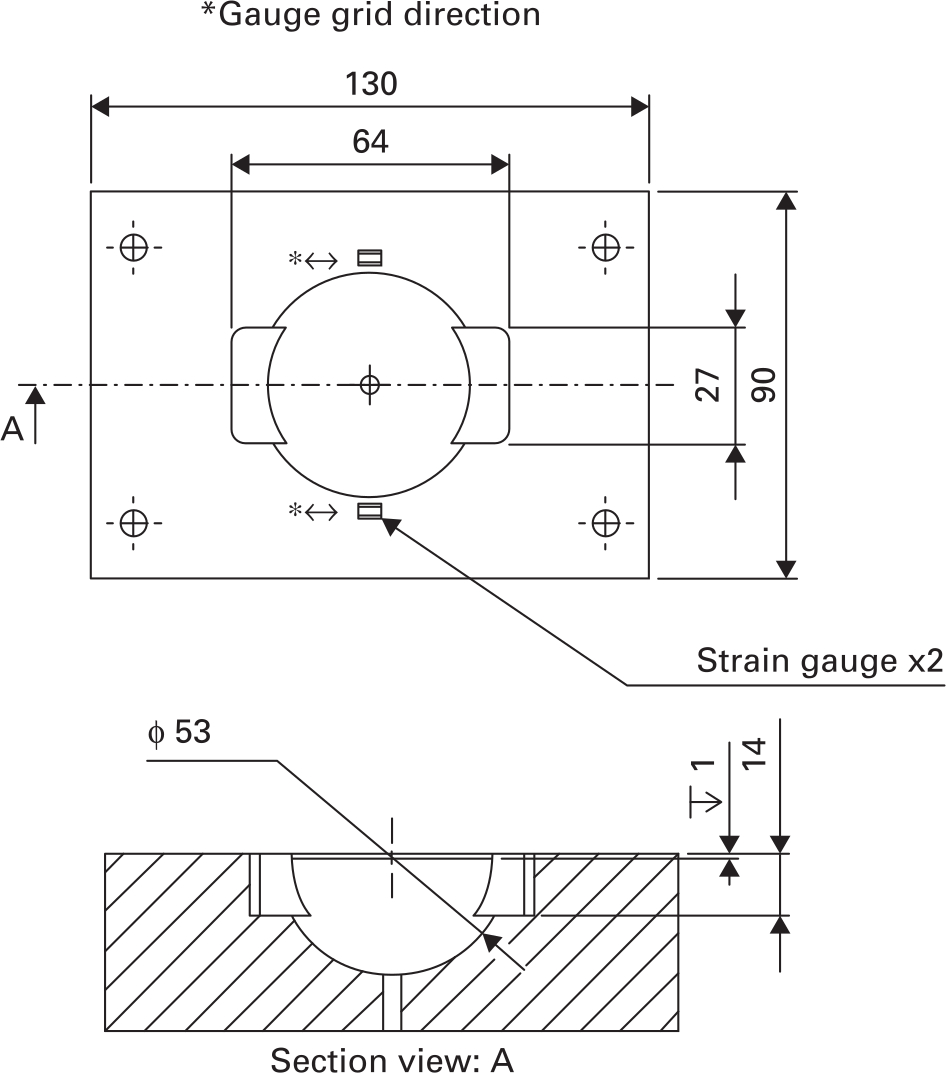
Fig. 2
Synthetic bone cavity geometry and strain gauge placement.
Implant stability: strain deterioration
Pilot testing indicated a characteristic pattern to the strain with an increasing number of strikes (Figure 3): initially strain increased strike by strike (Figure 3a), which represents an increase in the stability of the implant.31 This was followed by an inflexion point (peak strain) and a subsequent deterioration of strain with each strike (Figure 3b). This deterioration in strain with subsequent strikes was quantified and analyzed as it poses a clinical risk: over-impacting the component may reduce implant stability. A metric of strain reduction, hereby known as strain deterioration, is defined by the following equation, with terms defined graphically in Figure 3.
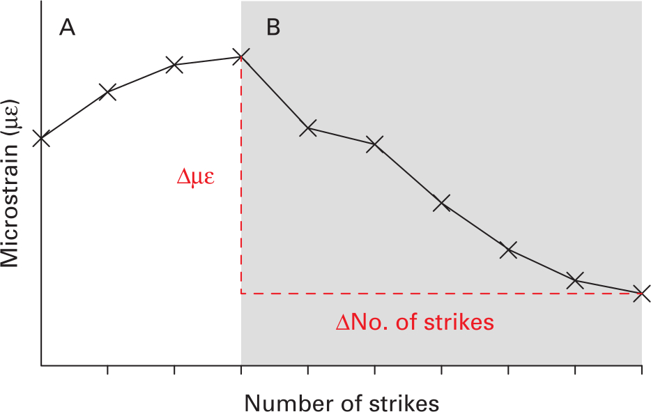
Fig. 3
Representative bone microstrain measurements during seating. An increase of strain is observed (A), followed by an inflexion point and subsequent deterioration (B).
A strain deterioration of zero would represent conditions where an excessive number of strikes beyond some optimum does not reduce bone strain at all. A larger strain deterioration magnitude represents conditions where excessive strikes cause a larger reduction in bone strain, and therefore reduction in component stability.
Implant stability: pushout
Pushout fixation was measured as an adjunct to bone strain as both are shown to relate to stability and correlate well.31 Pushout fixation was measured for two conditions. The first was after ten strikes for all mass, velocity, and bone density setups. The second was for optimum number of strikes, when the implant could be considered ‘seated’. This was when the implant had progressed by no more than 0.1 mm during the previous strike (see ‘Seating: polar gap’ for measurement method). A material testing machine (Instron model 5565; Instron, High Wycombe, UK) pushed components out at 0.5 mm per minute using a ø6 mm diameter steel rod through a 7 mm diameter entry hole milled into the synthetic bone at the pole of the component. Peak load was recorded. The pushout after ten strikes was always less than the ‘seated’ number of strikes, due to the strain deterioration illustrated in Figure 3. A pushout deterioration was then defined in the following equation:
Seating: polar gap
Two sets of infrared reflective markers were attached to the component introducer and impact platen (Figure 1), allowing their relative positions to be measured by an optical tracker (fusionTrack 500; Atracsys, Puidoux, Switzerland). Following ten strike seating the final polar gap of each specimen was measured using a depth gauge micrometer. Superposition of final polar gap and relative component movement during seating was used to calculate polar gap following each strike. Using these data the ‘optimum number of strikes’ for each impaction setup could be recorded.
Statistical analysis
Low-density bone data were tested for normality using a Shapiro-Wilk test in SPSS v24 (IBM, Armonk, New York, USA). Data were then analyzed with a two-way repeated measures analysis of variance with strain deterioration as the dependent variable and mallet mass (low, medium, high) and strike velocity (low, medium, high) as independent variables. The significance level was set to p < 0.05. Post-hoc paired t-test with Bonferroni correction was applied when differences across tests were found. Adjusted p-values, multiplied by the appropriate Bonferroni correction factor in SPSS, have been reported rather than reducing the significance level. A linear regression analysis was also performed to determine if a relationship exists between strain and pushout deterioration. Polar gap data were analyzed with paired t-tests. These analyses were then repeated for the high-density bone data.
Results
Implant stability: strain deterioration
For both bone densities, at all velocities and all mass strikes, implant impaction was characterized by a period of increasing bone strain, followed by an inflection point and then by strain deterioration (Figure 4). This severity of the peak and strain deterioration is observed to varying degrees depending upon the mass/velocity strike combination. In the most extreme case with low-density bone, high strike mass, and high strike velocity, the peak strain was generated after one strike; the second strike then halved the strain, and the third strike reduced the strain to zero (Figure 4c).
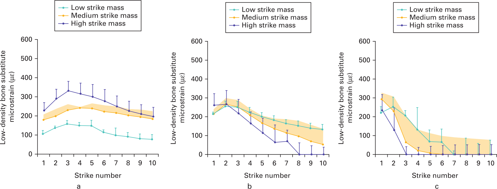
Fig. 4
Mean microstrain measured (with SD) post-strike for low-density bone at a) low, b) medium, and c) high velocities. Strains are characterized by increasing strain, an inflexion point, and strain reduction.
For low-density bone, the effects of mallet mass upon strain deterioration depended upon the strike velocity (interaction p = 0.007) (Figure 5). At low velocity, all the strain deterioration values were low (-8 to -17) and the effect of strike mass was low (maximum difference -9; p = 0.070). Conversely, at high strike velocities the strain deterioration was much higher (-42 to -78) and the effects of strike mass were much greater (maximum difference -36; p < 0.005). This indicates that low velocities were less sensitive to over-impaction and that increasing strike mass at low velocity in low-density bone does not increase the strain deterioration if too many strikes are used. For high-density bone strain deterioration magnitudes were low (-2 to -19; Supplementary Figure a), indicating that strain deterioration poses a greater clinical risk for low-density bone.
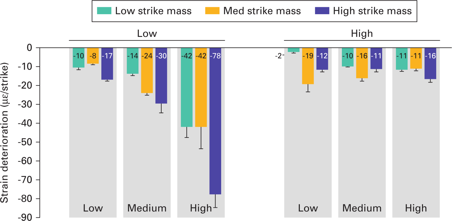
Fig. 5
Mean strain deterioration (with SD) for each impaction technique. Strain deterioration was greatest for lower-density bone, and for medium- or high-velocity strikes.
Implant stability: pushout
The number of strikes until the ‘optimally seated’ condition and pushout values are provided in Table I. For the group that were pushout tested when ‘optimally seated’, fixation increased with both strike mass and velocity. However, in the ten-strike group an increase in fixation with increasing mallet mass was only observed in the low velocity group. In the medium and high velocity group no increase in fixation was observed with mallet mass (Table I). Pushout deterioration is plotted as a function of strain deterioration (Figure 6; R2 = 0.83, p < 0.05). These data confirmed that strain deterioration was an appropriate measure for risk of component loosening, as fixation strength reduced linearly with strain deterioration.
Table I.
Number of strikes required for ‘seated’ condition and mean pushout values for each strike combination.
| Strike velocity | Low | Medium | High | ||||||
|---|---|---|---|---|---|---|---|---|---|
| Strike mass | Low | Med | High | Low | Med | High | Low | Med | High |
| Number of strikes to seat | 10* | 10* | 6 | 7 | 4 | 2 | 3 | 2 | 2 |
| Mean pushout value (seated), N (SD) | 123 (12) | 248 (16) | 442 (38) | 289 (46) | 356 (77) | 496 (22) | 368 (10) | 442 (79) | 630 (65) |
| Mean pushout value (10 strikes), N (SD) | 123 (12) | 248 (16) | 362 (18) | 172 (19) | 127 (48) | 90 (18) | 45 (14) | 60 (14) | 49 (6) |
-
*
< 0.1 mm displacement at tenth strike.
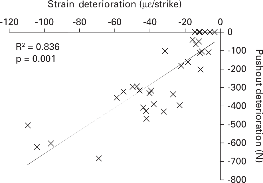
Fig. 6
Relationship between strain and pushout deterioration. Larger magnitude strain deterioration correlates with a reduction in pushout. Strain deterioration should be avoided to ensure optimum fixation.
Seating: polar gap
Polar gap reduced with both increasing mallet mass and velocity in both low- and high-density bone in all but the high velocity, high density group (Figure 7). A difference in polar gap between low and high mallet mass was detected (0.335 mm; p = 0.014) but not between low/medium and medium/high masses. Combining the findings of Figures 5 and 7 across the low- and high-density bone materials, the only mass/velocity combination that provided a low strain deterioration and full implant seating (polar gap ≤ 1 mm) was the high mallet mass at low velocity.
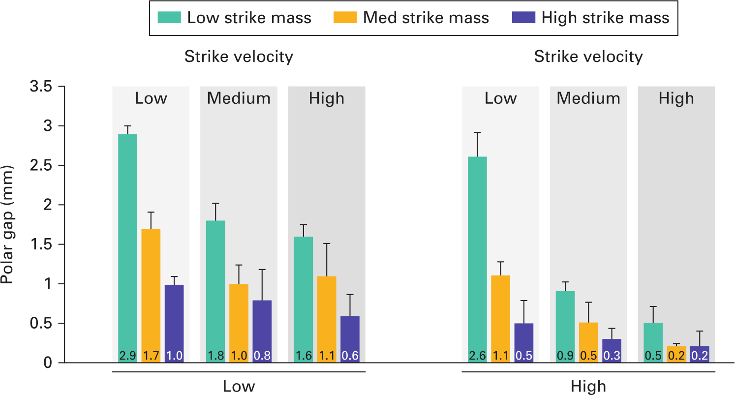
Fig. 7
Mean polar gaps at seating (with SD) for each impaction technique. Polar gap is reduced with both increasing impact mass and velocity.
Discussion
The most important finding of this study was that the strain in bone deteriorated after a certain number of impaction strikes, and that impaction technique had a large effect on this deterioration. A deterioration in strain was measured in all cases, but was most severe in the case of lower density bone (representing revision or poor-quality bone cases). This deterioration correlated well with a reduction in implant stability and so must be avoided. The strike velocity, which can be interpreted as how hard the surgeon hits the introducer, was a key risk factor for this deterioration – at high velocity even the lightest 0.6 kg mallet caused a severe deterioration in strain with excessive impaction strikes. At low velocity, for all mallet masses the deterioration in strain still occurred but was far less severe than at medium or high velocity. Therefore, a lower strike velocity may be preferable. It should also be considered that polar gaps of more than 2 mm have been linked to an increase in early component migration,50 while gaps of less than 2 mm have been deemed clinically acceptable46 and the gaps of 1 mm or less have been observed to be filled without intervention.51 A high mallet mass, coupled with a low strike velocity, minimizes strain deterioration while achieving < 1 mm polar gap and 66% of stability attained by the technique with the highest risk of strain deterioration.
This study demonstrates that high velocity mallet strikes achieve good implant stability, but only if the correct number of strikes are used. However, it has previously been shown that it is difficult for surgeons to accurately pinpoint when an implant is most effectively seated (i.e. the inflection points in Figure 3).32 Therefore if high-velocity strikes are used to seat components in low-density bone, extreme care should be taken to avoid an excessive number of strikes.
A synthetic bone model was used for this study. It is acknowledged that an isotropic material does not represent the anatomical complexity of the pelvis. However, cadaveric bone strength, stiffness, density, acetabular socket size, and rim anatomy all vary with specimen. A cadaveric repeated measures study design is also not possible due to the damage seating a component does to a specimen, preventing repeat testing. A synthetic model was chosen over cadaveric tissues to allow isolation of several variables and to perform meaningful analysis on the results. Every effort has been made to best represent the clinical scenario. Previous literature demonstrates the value of these models to draw important conclusions.41,44,52 Synthetic bone densities were carefully chosen using existing literature in order to most closely represent high-density (mostly cortical in primary THA) and low-density (more sub-chondral/defected) bone.20,34-36,38 While the model does not mimic the overall anatomy of the pelvis, the ‘notch’ model has been rigorously validated against cadaveric tissue in literature, providing mechanical properties,53,54 component deformation,39 component frictional resistance,20 and stability55 within the variability of mechanical samples, even when damaged.56 Therefore the key ‘pinching’ mechanism of the acetabulum is represented.39 The mechanism of the most important finding of this study (a deterioration of strain with excessive strikes) is likely due to the elastic nature of bone and the compliance of the hip during impact – two properties represented and validated for the model used.33 A second limitation is that pushout loading is not a physiological method of loading. However, it does test peripheral fixation effectively, and has been shown to produce similar results to other fixation testing methods.21,35,57
It is proposed that two previously reported phenomena contribute to the loss of stability measured when using too many high-velocity strikes. The first is damage to the bone during each strike.58 As the component is seated the bone surface layer is overly compacted/abraded by the component surface, reducing effective interference fit between component and bone. The increased yield strength of the higher-density bone, resisting damage, may contribute to its increased tolerance of high energy impacts (before strain deterioration occurs). Similarly, in low-impact energy scenarios (such as in the low velocity group) bone may not be sufficiently damaged to contribute to deterioration. Higher mallet mass may be preferable as mallet momentum is increased (aiding implant seating) without largely increasing energy (therefore limiting bone damage). In addition to bone damage, a ‘bounce back’ of an acetabular component out of the bone cavity has been identified in a previous study that employs dynamic testing techniques.39 Mid-strike, elastic energy is stored in the acetabular cavity and surrounding soft tissues. As the force of the hammer strike is released the component is subject to an ‘extraction’ force and can displace out of the bone cavity. Hothi et al48 observed this phenomenon during higher-velocity strikes, but only in dynamic models. It has been previously shown that the acetabulum undergoes significant acceleration during impact,33 which could produce an extraction force when experienced by introducer/component couplings with appreciable mass. Supplementary Video ii highlights the oscillation of the component/introducer construct within the acetabular cavity. Such mechanisms of elastic strain and acetabulum acceleration are known to occur in the in vivo environment, and therefore the mechanism of strain and stability deterioration demonstrated in this study warrants further investigation.
In conclusion, inadequate implant stability in revision THA or primary cases with poor bone stock remains a challenge for orthopaedic surgeons, with second revisions often required if adequate stability is not achieved. This study assesses how surgical technique may improve fixation. The in vitro model presented has indicated that surgeons should take great care if high-velocity strikes are used (even with a low mallet mass) to seat components in low density, as stability may be reduced if excessive impact strikes are used. The use of low strike velocity (1.5 m/s) and high mallet mass (1.8 kg) may mitigate a risk of loss of implant stability when impacting components into low-density bone, while ensuring the implant is seated well enough to promote effective bone ingrowth.
References
1. Editorial Board NJR . NJR 11th Annual Report 2014. National Joint Registry (England, Wales and Northern Island) . http://www.njrcentre.org.uk/njrcentre/Portals/0/Documents/England/Reports/11th_annual_report/NJR%2011th%20Annual%20Report%202014.pdf (date last accessed 11 June 2020 ). Google Scholar
2. Graves S , De Steiger R , Lewis P , et al. Australian Orthopaedic Association National Joint Replacement Registry. Aust Orthop Assoc Natl Jt Regist , 2014 . Google Scholar
3. American Joint Replacement Registry . Third AJRR Annual Report on Hip and Knee Arthroplasty Data , 2016 . Google Scholar
4. Pedersen AB , Fenstad AM . Nordic Arthroplasty Register Association (NARA) Report . 2016 . http://nrlweb.ihelse.net/NARA_2015_ORIG_ny.pdf (date last accessed 11 June 2020 ). Google Scholar
5. McMinn DJW , Snell KIE , Daniel J , et al. Mortality and implant revision rates of hip arthroplasty in patients with osteoarthritis: registry based cohort study . BMJ . 2012 ; 344 ( June ): e3319 . Crossref PubMed Google Scholar
6. Kendal AR , Prieto-Alhambra D , Arden NK , Carr A , Judge A . Mortality rates at 10 years after metal-on-metal hip resurfacing compared with total hip replacement in England: retrospective cohort analysis of hospital episode statistics . BMJ . 2013 ; 347 ( November ): f6549 . Crossref PubMed Google Scholar
7. Della Valle CJ , Berger RA , Rosenberg AG , Galante JO . Cementless acetabular reconstruction in revision total hip arthroplasty . Clin Orthop Relat Res . 2004 ; 420 ( 420 ): 96 – 100 . Crossref PubMed Google Scholar
8. Brubaker SM , Brown TE , Manaswi A , et al. Treatment options and allograft use in revision total hip arthroplasty the acetabulum . J Arthroplasty . 2007 ; 22 ( 7 Suppl 3 ): 52 – 56 . Crossref PubMed Google Scholar
9. Kim YH . Acetabular Cup Revision . Hip Pelvis . 2017 ; 29 ( 3 ): 155 – 158 . Google Scholar
10. NJR Editorial Board . 14th Annual Report 2017. National Joint Registry for England, Wales, Northern Ireland and the Isle of Man . https://www.hqip.org.uk/wp-content/uploads/pelerous_media_manager/public/253/NJR/NJR%2014th%20Annual%20Report%202017.pdf (date last accessed 11 June 2020 ). Google Scholar
11. Morscher E , Bereiter H , Lampert C . Cementless press-fit cup. Principles, experimental data, and three-year follow-up study . Clin Orthop Relat Res . 1989 ; 249 ( 249 ): 12 – 20 . PubMed Google Scholar
12. Morscher E , Masar Z . Development and first experience with an uncemented press-fit cup . Clin Orthop Relat Res . 1988 ; 232 : 96 – 103 . PubMed Google Scholar
13. Sundfeldt M , Carlsson LV , Johansson CB , Thomsen P , Gretzer C . Aseptic loosening, not only a question of wear: a review of different theories . Acta Orthop . 2006 ; 77 ( 2 ): 177 – 197 . Internet . Google Scholar
14. Pilliar RM , Lee JM , Maniatopoulos C . Observations on the effect of movement on bone ingrowth into porous-surfaced implants . Clin Orthop Relat Res . 1986 ; 208 : 108 – 113 . PubMed Google Scholar
15. Pulido L , Rachala SR , Cabanela ME . Cementless acetabular revision: past, present, and future. Revision total hip arthroplasty: the acetabular side using cementless implants . Int Orthop . 2011 ; 35 ( 2 ): 289 – 298 . Crossref PubMed Google Scholar
16. Boughton OR , Ma S , Cai X , et al. Computed tomography porosity and spherical indentation for determining cortical bone millimetre-scale mechanical properties . Sci Rep . 2019 ; 9 ( 1 ): 7416 . Crossref PubMed Google Scholar
17. Dumont GD , Zide JR , Huo MH . Periprosthetic femur fractures: current concepts and management . Semin Arthroplasty . 2010 ; 21 ( 1 ): 9 – 13 . Google Scholar
18. Springer BD , Fehring TK , Griffin WL , Odum SM , Masonis JL . Why revision total hip arthroplasty fails . Clin Orthop Relat Res . 2009 ; 467 ( 1 ): 166 – 173 . Crossref PubMed Google Scholar
19. Haidukewych GJ , Jacofsky DJ , Hanssen AD , Lewallen DG . Intraoperative fractures of the acetabulum during primary total hip arthroplasty . J Bone Joint Surg Am . 2006 ; 88-A ( 9 ): 1952 – 1956 . Crossref PubMed Google Scholar
20. Fritsche A , Bialek K , Mittelmeier W , et al. Experimental investigations of the insertion and deformation behavior of press-fit and threaded acetabular cups for total hip replacement . J Orthop Sci . 2008 ; 13 ( 3 ): 240 – 247 . Crossref PubMed Google Scholar
21. Ries MD , Harbaugh M , Shea J , Lambert R . Effect of cementless acetabular cup geometry on strain distribution and press-fit stability . J Arthroplasty . 1997 ; 12 ( 2 ): 207 – 212 . Crossref PubMed Google Scholar
22. Perona PG , Lawrence J , Paprosky WG , Patwardhan AG , Sartori M . Acetabular micromotion as a measure of initial implant stability in primary hip arthroplasty. An in vitro comparison of different methods of initial acetabular component fixation . J Arthroplasty . 1992 ; 7 ( 4 ): 537 – 547 . Crossref PubMed Google Scholar
23. Markel DC , Hora N , Grimm M . Press-fit stability of uncemented hemispheric acetabular components: a comparison of three porous coating systems . Int Orthop . 2002 ; 26 ( 2 ): 72 – 75 . Crossref PubMed Google Scholar
24. Dold P , Pandorf T , Flohr M , et al. Acetabular shell deformation as a function of shell stiffness and bone strength . Proc Inst Mech Eng H . 2016 ; 230 ( 4 ): 259 – 264 . Crossref PubMed Google Scholar
25. Hsu JT , Chang CH , Huang HL , et al. The number of screws, bone quality, and friction coefficient affect acetabular cup stability . Med Eng Phys . 2007 ; 29 ( 10 ): 1089 – 1095 . Crossref PubMed Google Scholar
26. Kim YS , Callaghan J , Ahn P , Brown T . Fracture of the Acetabulum during Insertion of an Oversized Hemispherical Component . J Bone Joint Surg Am . 1995 ; 77-A ( 1 ): 111 – 117 . Crossref PubMed Google Scholar
27. Curtis MJ , Jinnah RH , Wilson VD , Hungerford DS . The initial stability of uncemented acetabular components . J Bone Joint Surg Br . 1992 ; 74-B ( 3 ): 372 – 376 . Crossref PubMed Google Scholar
28. Winter W , Karl M . Basic considerations for determining the amount of press fit in acetabular cup endoprostheses as a function of the elastic bone behavior . Biomed Tech (Berl) . 2014 ; 59 ( 5 ): 413 – 420 . Crossref PubMed Google Scholar
29. Campi S , Mellon SJ , Ridley D , et al. Optimal interference of the tibial component of the cementless Oxford Unicompartmental Knee Replacement . Bone Joint Res . 2018 ; 7 ( 3 ): 226 – 231 . Crossref PubMed Google Scholar
30. Sporer S , MacLean L , Burger A , Moric M . Evaluation of a 3D-printed total knee arthroplasty using radiostereometric analysis . Bone Joint J . 2019 ; 101-B ( 7_Supple_C ): 40 – 47 . Crossref PubMed Google Scholar
31. Doyle R , van Arkel RJ , Jeffers JRT . Effect of impaction energy on dynamic bone strains, fixation strength, and seating of cementless acetabular cups . J Orthop Res . 2019 ; 37 ( 11 ): 2367 – 2375 . Crossref PubMed Google Scholar
32. Kroeber M , Ries MD , Suzuki Y , et al. Impact biomechanics and pelvic deformation during insertion of press-fit acetabular cups . J Arthroplasty . 2002 ; 17 ( 3 ): 349 – 354 . Crossref PubMed Google Scholar
33. Doyle R , Boughton O , Plant D , et al. An in vitro model of impaction during hip arthroplasty . J Biomech . 2019 ; 82 : 220 – 227 . Crossref PubMed Google Scholar
34. Adler E , Stuchin SA , Kummer FJ . Stability of press-fit acetabular cups . J Arthroplasty . 1992 ; 7 ( 3 ): 295 – 301 . Crossref PubMed Google Scholar
35. Crosnier EA , Keogh PS , Miles AW . A novel method to assess primary stability of press-fit acetabular cups . Proc Inst Mech Eng H . 2014 ; 228 ( 11 ): 1126 – 1134 . Crossref PubMed Google Scholar
36. Baleani M , Fognani R , Toni A . Initial stability of a cementless acetabular cup design: experimental investigation on the effect of adding fins to the rim of the cup . Artif Organs . 2001 ; 25 ( 8 ): 664 – 669 . Crossref PubMed Google Scholar
37. Fritsche A , Zietz C , Teufel S , et al. A851. in-vitro and in-vivo investigations of the impaction and PULL-OUT behavior of METAL-BACKED acetabular CUPS . Orthopaedic Proceedings . 2011 ; 93-B ( SUPP_IV ): 406 – 406 . Google Scholar
38. Small SR , Berend ME , Howard LA , et al. Acetabular cup stiffness and implant orientation change acetabular loading patterns . J Arthroplasty . 2013 ; 28 ( 2 ): 359 – 367 . Crossref PubMed Google Scholar
39. Lin ZM , Meakins S , Morlock MM , et al. Deformation of press-fitted metallic resurfacing cups. Part 1: experimental simulation . Proc Inst Mech Eng H . 2006 ; 220 ( 2 ): 299 – 309 . Crossref PubMed Google Scholar
40. Hothi HS , Busfield JJC , Shelton JC . Deformation of uncemented metal acetabular cups following impaction: experimental and finite element study . Comput Methods Biomech Biomed Engin . 2014 ; 17 ( 11 ): 1261 – 1274 . Crossref PubMed Google Scholar
41. Meding JB , Small SR , Jones ME , Berend ME , Ritter MA . Acetabular cup design influences deformational response in total hip arthroplasty . Clin Orthop Relat Res . 2013 ; 471 ( 2 ): 403 – 409 . Crossref PubMed Google Scholar
42. Ong KL , Rundell S , Liepins I , et al. Biomechanical modeling of acetabular component polyethylene stresses, fracture risk, and wear rate following press-fit implantation . J Orthop Res . 2009 ; 27 ( 11 ): 1467 – 1472 . Crossref PubMed Google Scholar
43. Squire M , Griffin WL , Mason JB , Peindl RD , Odum S . Acetabular Component Deformation with Press-Fit Fixation . J Arthroplasty . 2006 ; 21 ( 6 Suppl 2 ): 72 – 77 . Crossref PubMed Google Scholar
44. van Arkel RJ , Ghouse S , Milner PE , Jeffers JRT . Additive manufactured push-fit implant fixation with screw-strength pull out . J Orthop Res . 2018 ; 36 ( 5 ): 1508 – 1518 . Crossref PubMed Google Scholar
45. MacKenzie JR , Callaghan JJ , Pedersen DR , Brown TD . Areas of contact and extent of gaps with implantation of oversized acetabular components in total hip arthroplasty . Clin Orthop Relat Res . 1994 ; 298 ( 298 ): 127 – 136 . PubMed Google Scholar
46. Schmalzried TP , Wessinger SJ , Hill GE , Harris WH . The Harris-Galante porous acetabular component press-fit without screw fixation. Five-year radiographic analysis of primary cases . J Arthroplasty . 1994 ; 9 ( 3 ): 235 – 242 . Crossref PubMed Google Scholar
47. Maharaj G , Jamison R . Intraoperative Impact: Characterization and Laboratory Simulation on Composite Hip prostheses. In: Jamison R, Gilbertson L, eds . STP1178-EB Composite Materials for Implant Applications in the Human Body: Characterization and Testing , 1993 : 98 – 108 . Google Scholar
48. Hothi HS , Busfield JJC , Shelton JC . Explicit finite element modelling of the impaction of metal press-fit acetabular components . Proc Inst Mech Eng H . 2011 ; 225 ( 3 ): 303 – 314 . Crossref PubMed Google Scholar
49. Scholl L , Schmidig G , Faizan A , TenHuisen K , Nevelos J . Evaluation of surgical impaction technique and how it affects locking strength of the head-stem taper junction . Proc Inst Mech Eng H . 2016 ; 230 ( 7 ): 661 – 667 . Crossref PubMed Google Scholar
50. Nakasone S , Takao M , Nishii T , Sakai T , Sugano N . Incidence and Natural Course of Initial Polar Gaps in Birmingham Hip Resurfacing Cups . J Arthroplasty . 2012 ; 27 ( 9 ): 1676 – 1682 . Crossref PubMed Google Scholar
51. Udomkiat P , Dorr LD , Wan Z . Cementless hemispheric porous-coated sockets implanted with press-fit technique without screws: Average ten-year follow-up . J Bone Jt Surg . 2002 ; 84 ( 7 ): 1195 – 1200 . Crossref PubMed Google Scholar
52. Wiznia DH , Joyal G , Schmidig G , et al. The Effect of Interposed Tissue and Contamination on the Initial Stability of a Highly Porous Press-Fit Acetabular Cup . J Orthop Res . 2019 ; 37 ( 5 ): 1117 – 1122 . Google Scholar
53. Szivek JA , Thomas M , Benjamin JB . Characterization of a synthetic foam as a model for human cancellous bone . J Appl Biomater . 1993 ; 4 ( 3 ): 269 – 272 . Crossref PubMed Google Scholar
54. Marter AD , Dickinson AS , Pierron F , Fong YKK , Browne M . Characterising the compressive anisotropic properties of analogue bone using optical strain measurement . Proc Inst Mech Eng H . 2019 ; 233 ( 9 ): 954 – 960 . Crossref PubMed Google Scholar
55. Crosnier EA , Keogh PS , Miles AW . The effect of dynamic hip motion on the micromotion of press-fit acetabular cups in six degrees of freedom . Med Eng Phys . 2016 ; 38 ( 8 ): 717 – 724 . Crossref PubMed Google Scholar
56. Ayers MP , Clift SE , Gheduzzi S . Morsellised sawbones is an acceptable experimental substitute for the in vitro elastic and viscoelastic mechanical characterisation of morsellised cancellous bone undergoing impaction grafting . Med Eng Phys . 2014 ; 36 ( 1 ): 26 – 31 . Crossref PubMed Google Scholar
57. Macdonald W , Carlsson LV , Charnley GJ , Jacobsson CM . Press-fit acetabular cup fixation: principles and testing . Proc Inst Mech Eng H . 1999 ; 213 ( 1 ): 33 – 39 . Crossref PubMed Google Scholar
58. Bishop NE , Höhn JC , Rothstock S , Damm NB , Morlock MM . The influence of bone damage on press-fit mechanics . J Biomech . 2014 ; 47 ( 6 ): 1472 – 1478 . Crossref PubMed Google Scholar
Author contributions
R. Doyle: Designed the study, Conducted the experiment setup, Analyzed the data, Wrote and revised the manuscript.
R. J. van Arkel: Conducted the experiment setup, Wrote and revised the manuscript.
S. Muirhead-Allwood: Wrote and revised the manuscript.
J. R. T. Jeffers: Designed the study, Wrote and revised the manuscript.
Funding statement
The institution of one or more of the authors (JRTJ, RD) has received funding from Desoutter Medical (the Cooperative Award in Science and Engineering (CASE) studentship), the Wellcome Trust (208858/Z/17/Z), and an Engineering and Physical Sciences Research Committee grant (ref: EP/K027549/1).
Although none of the authors has received or will receive benefits for personal or professional use from a commercial party related directly or indirectly to the subject of this article, benefits have been or will be received but will be directed solely to a research fund, foundation, educational institution, or other non- profit organization with which one or more of the authors are associated.
ICMJE COI statement
None declared.
Acknowledgements
The project was funded by DeSoutter Medical Ltd., the Engineering and Physical Sciences Research Council (EP/K027549/1), and the Wellcome Trust (208858/Z/17/Z).
Ethical review statement
No human tissues were used for this study.
Supplementary material
A number of items of supplementary material are provided for further information for the reader. These include: 1) a video to demonstrate the impaction velocities used for this study as applied by the surgeon, for ‘real world’ reference; 2) a figure showing post-strike strain values for high-density bone to complement Figure 4; and 3) a high-speed video to demonstrate the ‘bounce-back’ effect of the acetabular component in synthetic bone that may to contribute to strain deterioration and loosening.
© 2020 Author(s) et al. This is an open-access article distributed under the terms of the Creative Commons Attribution Non-Commercial No Derivatives (CC BY-NC-ND 4.0) licence, which permits the copying and redistribution of the work only, and provided the original author and source are credited. See https://creativecommons.org/licenses/by-nc-nd/4.0/.
