


Abstract
Aims
Appropriate acetabular component placement has been proposed for prevention of postoperative dislocation in total hip arthroplasty (THA). Manual placements often cause outliers in spite of attempts to insert the component within the intended safe zone; therefore, some surgeons routinely evaluate intraoperative pelvic radiographs to exclude excessive acetabular component malposition. However, their evaluation is often ambiguous in case of the tilted or rotated pelvic position. The purpose of this study was to develop the computational analysis to digitalize the acetabular component orientation regardless of the pelvic tilt or rotation.
Methods
Intraoperative pelvic radiographs of 50 patients who underwent THA were collected retrospectively. The 3D pelvic bone model and the acetabular component were image-matched to the intraoperative pelvic radiograph. The radiological anteversion (RA) and radiological inclination (RI) of the acetabular component were calculated and those measurement errors from the postoperative CT data were compared relative to those of the 2D measurements. In addition, the intra- and interobserver differences of the image-matching analysis were evaluated.
Results
Mean measurement errors of the image-matching analyses were significantly small (2.5° (SD 1.4°) and 0.1° (SD 0.9°) in the RA and RI, respectively) relative to those of the 2D measurements. Intra- and interobserver differences were similarly small from the clinical perspective.
Conclusion
We have developed a computational analysis of acetabular component orientation using an image-matching technique with small measurement errors compared to visual evaluations regardless of the pelvic tilt or rotation.
Cite this article: Bone Joint Res 2020;9(7):360–367.
Article focus
-
It is often difficult to evaluate the acetabular component position in the intraoperative pelvic radiograph in case of the tilted or rotated pelvic position.
-
To develop the computational analysis to digitalize the acetabular component orientation regardless of the pelvic tilt or rotation.
Key messages
-
We have developed a computational analysis of acetabular component orientation using an image-matching technique.
-
Measurement errors were small compared to visual evaluations regardless of the pelvic tilt or rotation.
Strengths and limitations
-
Our method can help the surgeon to confirm the acetabular component orientation regardless of the pelvic tilt or rotation during surgery.
-
Preoperative CT scan data are necessary, although CT-based 3D planning can help more precise placement of total hip arthroplasty (THA) components.
Introduction
Total hip arthroplasty (THA) has been a successful surgical procedure for hip disorders. One of the keys for implant longevity is to avoid dislocation and many surgeons make best efforts to prevent it (surgical approaches,1 appropriate soft tissue balance,2 and implant positions3). Optimal implant positions are also described as important factors for postoperative range of motion, implant stability such as polyethylene wear and osteolysis, impingement avoidance, and decrement of shearing force.4-7
Lewinnek et al8 proposed “a safe zone” of component placement with a mean radiological inclination angle (RI) of 40° (SD 10°) and a mean radiological anteversion angle (RA) of 15° (SD 10°) for prevention of postoperative dislocation 40 years ago. However, many articles have recently demonstrated little significance of the Lewinnek safe zone9-12 and suggested a new functional safe zone considering a combined anteversion technique6,13,14 and spinopelvic movement.15-17 This safe zone is often patient-specific and reported to be much narrower than previously believed,18,19 therefore surgeons should place the acetabular component more correctly based on the individualized preoperative planning. However, manual placements often cause outlier in spite of attempts to insert the component within the intended safe zone.20-22 Moreover, it is extremely difficult even for expert surgeons to place the acetabular component in the appropriate position in a freehand manner in cases of severe acetabular deformity caused by severe developmental dysplasia, hip arthrodesis, and others.23-25
Some surgeons take an intraoperative pelvic radiograph routinely after setting the acetabular component to confirm the placement.26,27 The acetabular component is placed under the assumption that the pelvis is near the neutral position. However, the intraoperative pelvic position is often tilted or rotated relative to the aimed one,28 and surgeons need to evaluate the component orientation relative to the tilted or rotated pelvic position visually. This visual evaluation has great ambiguity. It would be useful if surgeons could evaluate the component orientation digitally regardless of the pelvic tilt or rotation.
The purposes of this study were: 1) to develop a computational analysis to digitalize the acetabular component orientation from 2D radiographs using an existing image-matching technique; and 2) to evaluate its accuracy compared to the data from 3D analyses.
Methods
The study group was formed with 50 consecutive patients (50 hips) who underwent THA using one specific acetabular cementless component (AMS & PerFix HA; Kyocera, Osaka, Japan) with osteoarthritis (OA), rheumatoid arthritis, osteonecrosis of the femoral head, and subchondral insufficiency fracture (SIF) of the femoral head (Table I). All patients were Japanese and provided informed consent. The local Institutional Review Board approved this study.
Table I.
Patient details.
| Variable | Data (n = 50) |
|---|---|
| Mean age, yrs (SD) | 68.2 (11.3) |
| Sex, male:female, n | 3:47 |
| Side, right:left, n | 27:23 |
| Mean height, cm (SD) | 150.8 (5.9) |
| Mean body weight, kg (SD) | 53.0 (9.7) |
| Mean body mass index, kg/m2 (SD) | 23.2 (3.7) |
| Preoperative diagnosis, n | |
| Osteoarthritis | 45 |
| Rheumatoid arthritis | 1 |
| Osteonecrosis of the femoral head | 3 |
| Subchondral insufficiency fracture of the femoral head | 1 |
All THAs were performed in the lateral position through the posterolateral approach. The pelvis was fixed with bilateral anterior superior iliac spines (ASIS) and the sacrum. A preoperative pelvic radiograph was routinely taken just after setting the lateral position in our hospital. A portable radiograph device was set so that the irradiation origin was centered at the superior margin of the pubic symphysis. The film was held vertically and positioned at the back of the pelvis parallel to the trunk. The distance between the irradiation origin and the film was maintained consistently (180 cm). We adjusted the pelvic position carefully to match the aimed one by tilting or rotating an operating table.
The target angle of the acetabular component was generally set at an RA of 20° and an RI of 40° in our series. In some cases with larger or smaller femoral neck anteversion, RA was adjusted a little to keep combined anteversion.6,13,14
Definition of the 3D coordinate system in the pelvic model and acetabular component
Preoperative transverse CT scans (Revolution CT; GE Healthcare Japan, Tokyo, Japan) were taken at levels ranging from the whole pelvis to the knee joint at 1.25 mm intervals and 1.25 mm thickness with a field of view of 400 and pitch of 1.375 to make a preoperative 3D planning in all patients. CT images were acquired as Digital Imaging and Communications in Medicine format (DICOM) data from the CT system server, and DICOM datasets were imported into a 3D planning software (ZedHip; Lexi, Tokyo, Japan). 3D pelvic bone models were reconstructed and segmented with each femur in the software.
The anterior pelvic plane (APP) was defined as the plane including bilateral ASIS and the superior margin of the pubic symphysis (Figure 1a). The sagittal axis was corrected for the sagittal pelvic tilt in the supine position from that of the APP (Figure 1b), and this plane was defined as the functional pelvic plane (FPP).29,30 The FPP was embedded into each pelvic bone model and the origin was defined as the superior margin of the pubic symphysis. The y-axis was defined as the axis perpendicular to the FPP. The x-axis was defined as the axis included in the FPP and parallel to the line connecting bilateral ASIS. The direction of each axis is described in Figure 1c.
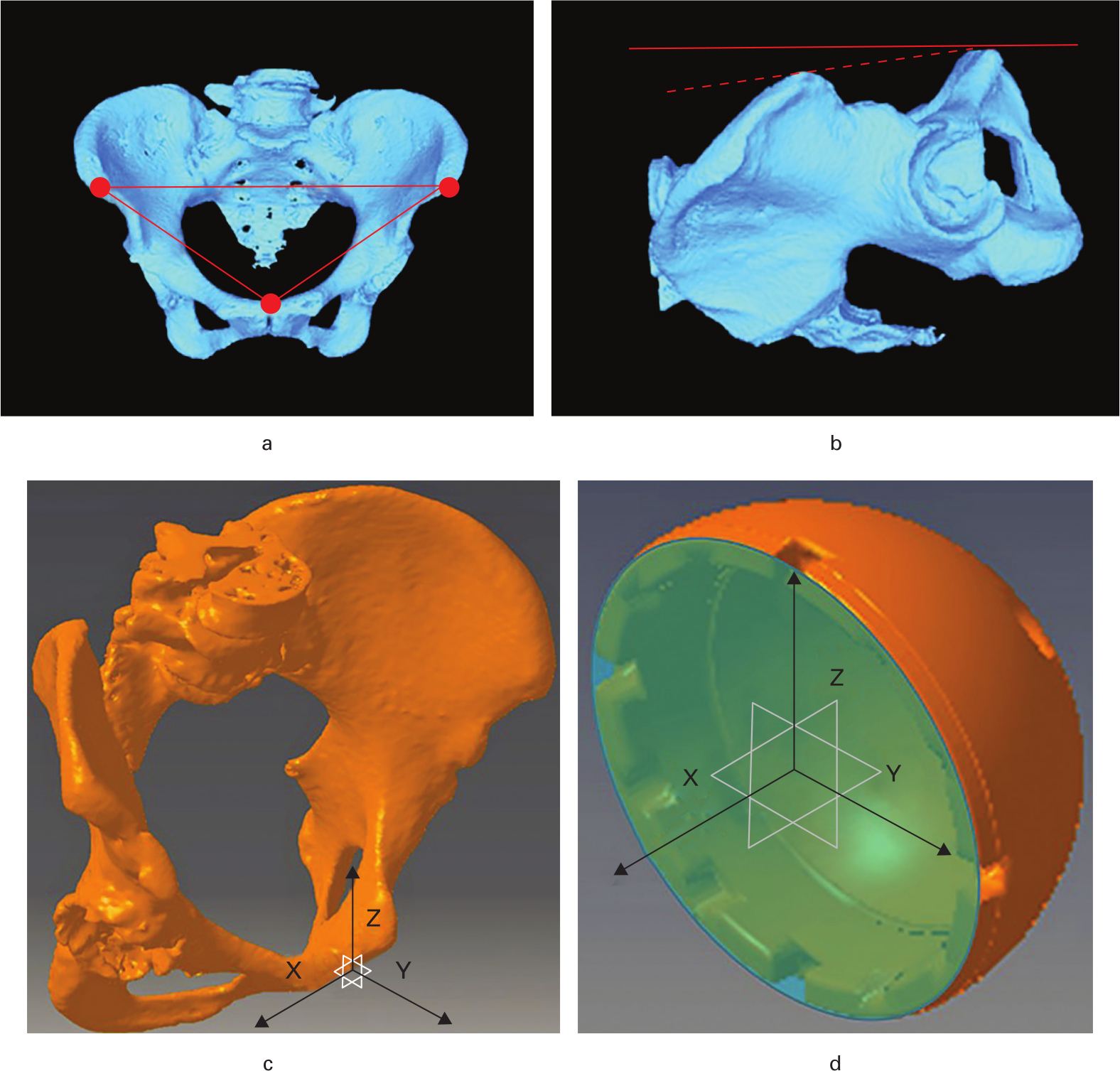
Fig. 1
Coordinate systems of the a) to c) pelvic bone and the d) acetabular component. a) The anterior pelvic plane (APP) including bilateral anterior superior iliac spines (ASIS) and the superior margin of the pubic symphysis (three points). b) The sagittal axis is corrected for the sagittal pelvic tilt in the supine position (solid line) from that of the APP (broken line), and this plane is defined as the functional pelvic plane (FPP). c) The FPP is defined as the XZ plane and the x-axis is parallel to the line connecting bilateral ASIS. d) The central axis perpendicular to the component opening plane (blue plane) is defined as the x-axis.
In the acetabular component, the centre of the component opening plane was defined as the origin and the central axis of the acetabular component perpendicular to the component opening plane was defined as the x-axis (Figure 1d).
Analyses of acetabular component orientation in the intraoperative pelvic radiograph
An image-matching technique has been developed and used for the kinematic analysis of each joint.31-36 The general methods are described below. Some objects were constructed as 3D models on the computer and image-matched to the edges of those objects in a 2D radiograph. The positions of each object were reconstructed three-dimensionally and the relative positional relationship of each object could be calculated.
An intraoperative pelvic radiograph including bilateral hips was routinely taken after setting the acetabular component and the femoral trial stem in our hospital. Intraoperative pelvic radiographs of all patients were collected retrospectively in this study. The 3D pelvic bone model and the acetabular component were image-matched to the intraoperative pelvic radiograph using the image-matching software (JointTrack; University of Florida, Gainesville, Florida, USA; Figures 2a to 2c). In the image-matching of the pelvic model, anatomical structures with distinctive shapes located around the centre of the radiograph (pubic symphysis, obturator foramina, pubis, ischium, and pelvic cavity) would help its precision. In the image-matching of the acetabular component, we fit the ellipse line made from the acetabular component edge very carefully. The pelvic tilt and rotation on the coronal, sagittal, and axial planes and the RA and RI of the acetabular component relative to the FPP were calculated from the image-matching data using the program as described in the Supplementary Material (i.e. image-matched RA and RI).
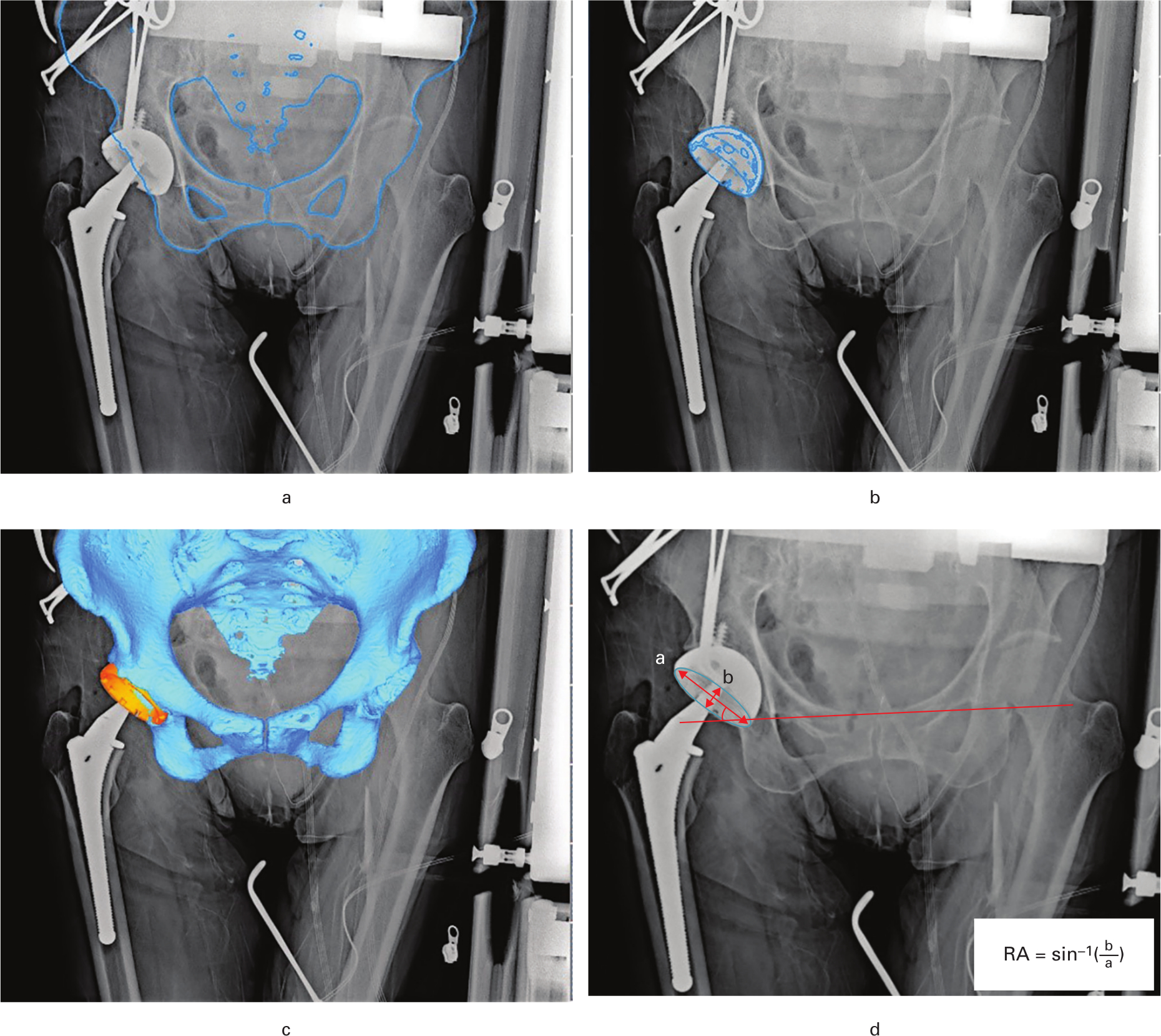
Fig. 2
a) The edge of the 3D pelvic bone model is image-matched to the perioperative pelvic radiograph using the image-matching software (JointTrack; University of Florida, Gainesville, Florida, USA). b) The edge of the 3D acetabular component is image-matched. c) 3D view of the pelvic bone model and the acetabular component. d) The radiological anteversion angle (RA) was calculated with the formula reported by Lewinnek et al,8 and the radiological inclination angle (RI) was measured as the angle between the line connecting both tear drops (solid line) and the long axis of the acetabular component (red arrow indicating “a”).
Then, the RA and RI were measured two-dimensionally with the same radiographs. The RA was calculated with the formula reported by Lewinnek et al8 and the RI was measured as the angle between the line connecting both tear drops and the long axis of the acetabular component (Figure 2d).
RA and RI measurements using postoperative CT
A postoperative CT scan was performed at two weeks after surgery in all cases to determine the postoperative component angle, and postoperative CT datasets were imported into a 3D planning software (3D Template; Kyocera). The preoperative FPP (reference pelvic plane during surgery) should be reproduced in RA and RI measurements. Therefore, the sagittal angle between the APP and FPP was measured in the preoperative CT data at first, then the preoperative FPP was reproduced in the postoperative CT data by adjusting the sagittal angle from the APP. The RA and RI of the acetabular component relative to the FPP were measured in the multiplanar reformat (MPR) images by two examiners (SK, T. Sato) (Figure 3), and their mean measurements of the RA and RI were adopted as the postoperative component angles (i.e. true RA and RI).
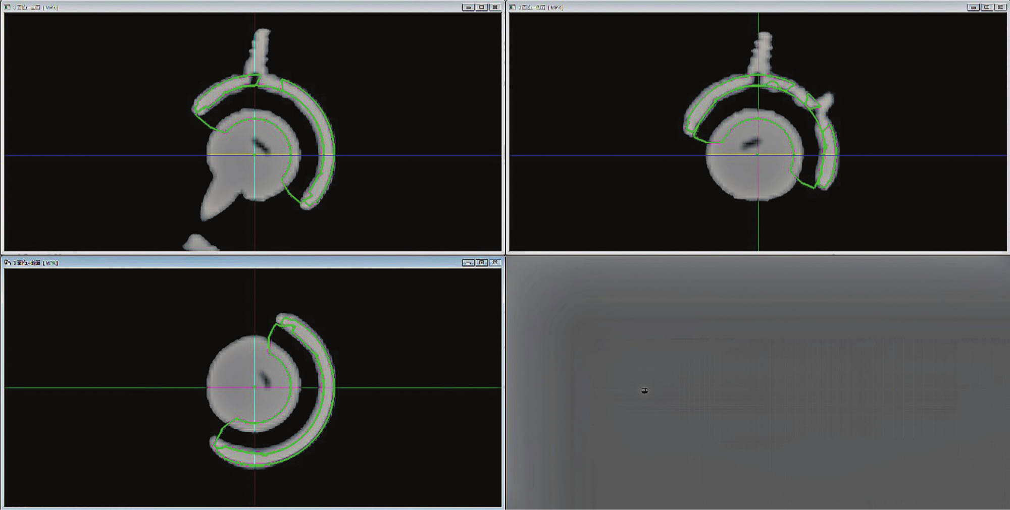
Fig. 3
The acetabular component is matched in the multiplanar reformat (MPR) images reconstructed from postoperative CT data, and the radiological anteversion angle (RA) and radiological inclination angle (RI) of the acetabular component relative to the functional pelvic plane (FPP) were measured.
RA and RI measurements from postoperative CT data were repeated twice at least one month apart for ten randomly extracted patients, and intra- and interobserver differences of those measurements were investigated. The intraclass correlation coefficient and the interclass correlation coefficient were all over 0.9, proving to be sufficiently reliable.
The RA and RI calculated from the image-matching analysis (image-matched RA and RI) and those measured two-dimensionally were compared with those measured from the postoperative CT (true RA and RI). The deviations were described as means and absolute values and compared with each other with a paired t-test. Significance was set at a p-value of < 0.05.
Intra- and inter-observer trials of the image-matching analysis
Image-matching analyses were repeated twice at least one month apart for ten randomly extracted patients, the first time by two surgeon examiners (SK and KK) and the second time by one surgeon examiner on the same ten patients (SK). Intra- and interobserver differences of the image-matched RA and RI were evaluated as the intraclass correlation coefficient and the interclass correlation coefficient, respectively.
Learning curve
One young orthopaedic surgeon (KK) who was not familiar with THA and our image-matching procedures did the same analyses. The time for completion of the image-matching procedure of the acetabular component and the pelvic model was measured, and the differences between his measurements and component angles measured from postoperative CT (true RA and RI) were calculated.
Results
Our results showed clinically high accuracy of component implantation. Mean pelvic tilt and rotation on the coronal, sagittal, and axial planes in the intraoperative pelvic radiograph calculated from the image-matching data were 1.8° (SD 1.4°), 2.7° (SD 2.0°), and 2.6 (SD 1.8°), respectively. Mean measurement errors of the image-matching analyses compared to the data obtained from postoperative CT were within 3° in the RA and within 1° in the RI and significantly small relative to those of the 2D measurements (Table II).
Table II.
Implantation angle of the acetabular component in each measurement and their measurement deviations.
| Variable | RA | RI |
|---|---|---|
| Mean target angle, ° (SD) | 21.4 (2.2) | 40.0 (0.0) |
| Implantation angle measured from postoperative CT (true RA and RI) (A), ° (SD) | 22.1 (4.4) | 40.9 (3.5) |
| Implantation angle calculated by image-matching analyses (image-matched RA and RI) (B), ° (SD) | 24.6 (4.5) | 41.0 (3.5) |
| Implantation angle measured two-dimensionally (C), ° (SD) | 18.0 (4.0) | 40.9 (3.1) |
| B-A, ° (SD) | 2.5 (1.4) | 0.1 (0.9) |
| C-A, ° (SD) | -4.1 (4.0) | 0.0 (2.2) |
| |B-A| (absolute value), ° (SD) | 2.5 (1.4)* | 0.1 (0.9)* |
| |C-A| (absolute value), ° (SD) | 4.7 (3.2)* | 1.8 (1.2)* |
-
*
p < 0.01, paired t-test.
-
RA, radiological anteversion angle; RI, radiological inclination angle.
Mean intra- and inter-observer differences of the image-matching analyses were 1.3° (SD 1.0°) and 1.5° (SD 1.1°) in the RA and 0.6° (SD 0.5°) and 0.9° (SD 0.5°) in the RI. The intraclass correlation coefficient and the interclass correlation coefficient were 0.90 and 0.89 in the RA and 0.93 and 0.91 in the RI.
The time for completion of the image-matching procedure of the acetabular component and the pelvic model performed by a young orthopaedic surgeon (KK) and his measurement differences compared to the data obtained from postoperative CT are shown in Figure 4.
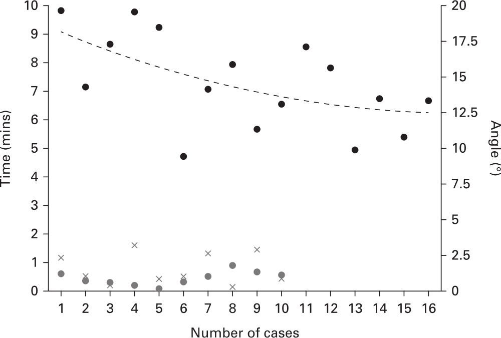
Fig. 4
The time for completion of the image-matching procedure of the acetabular component and the pelvic model performed by a young orthopaedic surgeon (KK) (time for each case: black point; approximate curve: black broken line) and his measurement differences compared to the data obtained from postoperative CT (radiological anteversion angle (RA): grey x-mark; radiological inclination angle (RI): grey point).
Discussion
Intraoperative evaluation of the acetabular component position using pelvic radiographs is useful for the purpose of excluding excessive malposition.37 However, even for expert surgeons visual evaluation has great ambiguity especially in the anteversion angle. A computational analysis to digitize the acetabular component orientation from 2D pelvic radiographs using an image-matching technique has been developed in this study.
Mean measurement errors of the image-matching analyses compared to the actual acetabular component angles were within 3° in the RA and within 1° in the RI. The RA is generally evaluated with the ellipse made from the acetabular component edge and might be overestimated slightly during the manual line fitting. However, it would be extremely difficult to evaluate the RA visually within the error range of 2° to 3° much more in cases of pelvic tilt or rotation. Some papers defined RA calculation methods based on the ratios of the ellipse on an anteroposterior pelvic radiograph.3,8,38,39 However, it is under the assumption that the pelvis keeps the neutral position. When we used the formula reported by Lewinnek et al,8 measurement errors of the image-matching analyses were significantly small relative to those of the 2D measurements. In addition, intra- and interobserver differences were similarly small in our method. Therefore, we believe our method can provide reliable and reproducible evaluations of the acetabular component orientation regardless of the pelvic tilt or rotation.
For clinical use in the future, another important question is whether any surgeons can use our method easily and speedily because they have to evaluate the acetabular component orientation intraoperatively. Measurement precisions of the RA and RI were stabilized in early series even for a young surgeon with the same as the results described above. The time required for analyses converged into six to seven minutes with experiences of approximately 15 cases; therefore our analysis would not extend the operation time so much.
Computer-assisted surgery (CAS) has been developed and clinically used for the last few decades. Computer-navigation systems are one of the major CAS items and much literature has described their accuracy in THA (Table III).40-44 Our measurement reliabilities are comparable to those of CT-based computer navigations and superior to those of image-free computer navigations. Our method cannot assist the accuracy of the acetabular cup placement directly; however, it can help the surgeon to confirm the acetabular component orientation during surgery.
Table III.
| Author | Navigation or method | Mean RA deviation, ° (SD) | Mean RI deviation, ° (SD) |
|---|---|---|---|
| Inaba et al40 | CT-based | 1.9 (1.9) | 2.2 (2.1) |
| Kajino et al41 | CT-based | 2.9 (1.8) | 1.5 (1.2) |
| Gurgel et al42 | Image-free | 5.5 (3.8) | 3.0 (1.8) |
| Lass et al43 | Image-free | 6.5 (3.7) | 3.2 (2.4) |
| Ybinger et al44 | Image-free | 6.5 (7.3) | 3.5 (4.4) |
| This study | Image-matching | 2.5 (1.4) | 0.1 (0.9) |
-
RA, radiological anteversion angle; RI, radiological inclination angle.
The current study has several limitations. First, preoperative CT scan data are necessary for reconstructing 3D pelvic bone models. However, they are originally taken to make a preoperative 3D planning in all patients regardless of this study. Several articles have demonstrated that preoperative planning with CT-based 3D templating achieved more precise placement of THA components,45-47 and preoperative CT for THA was associated with a slight but justifiable increase of radiation exposure in comparison to conventional radiographs and low per-patient costs.48 Second, plain pelvic radiographs were used during the image-matching procedure. Distortion-corrected radiographs such as radiographs taken with a flat panel device (FPD) should be used during the original image-matching procedure.31-34 However, it is not realistic to use FPD during surgery and surgeons have no choice but to use a portable radiograph device. The measurement errors of the image-matching analyses described above include both observer error itself and radiological distortion. Nevertheless, our method demonstrated clinically small errors compared to visual evaluations despite using a distortion uncorrected radiograph. In addition, interobserver differences were also small. Therefore, our method would be clinically relevant. Third, this is not a clinical study but a retrospective methodological study because the major objective was to develop the computational analysis to digitalize the acetabular component orientation from 2D radiographs using an image-matching technique. Therefore, it should be verified in the near future whether our method is useful during surgery. Fourth, patients implanted with one specific acetabular component were selected in our series because computer-aided design (CAD) data of the component were needed for image-matching. However, most acetabular components have hemispherical shapes and our method would be flexible to other implants. Last, our method in itself allows for measurement of version but does not specify whether the component is anteverted or retroverted. However, the trial liner in which some beads are embedded would show whether the component is anteverted or retroverted. We have not used these devices in our series, therefore they should be adopted in future studies.
In conclusion, we have developed a computational analysis of acetabular component orientation using an image-matching technique regardless of pelvic tilt or rotation with extremely small measurement errors compared to visual evaluations. The learning curve was relatively low even for young surgeons. A simple software should be developed so that surgeons can accomplish whole analysis procedures easily.
References
1. Kim YS , Kwon SY , Sun DH , Han SK , Maloney WJ . Modified posterior approach to total hip arthroplasty to enhance joint stability . Clin Orthop Relat Res . 2008 ; 466 ( 2 ): 294 – 299 . Crossref PubMed Google Scholar
2. Takao M , Nishii T , Sakai T , Sugano N . Postoperative Limb-Offset Discrepancy Notably Affects Soft-Tissue Tension in Total Hip Arthroplasty . J Bone Joint Surg Am . 2016 ; 98-A ( 18 ): 1548 – 1554 . Crossref PubMed Google Scholar
3. Hassan DM , Johnston GHF , Dust WNC , Watson G , Dolovich AT . Accuracy of intraoperative assessment of acetabular prosthesis placement . J Arthroplasty . 1998 ; 13 ( 1 ): 80 – 84 . Crossref PubMed Google Scholar
4. Schmalzried TP , Guttmann D , Grecula M , Amstutz HC . The relationship between the design, position, and articular wear of acetabular components inserted without cement and the development of pelvic osteolysis . J Bone Joint Surg Am . 1994 ; 76-A ( 5 ): 677 – 688 . Crossref PubMed Google Scholar
5. Kennedy JG , Rogers WB , Soffe KE , et al. Effect of acetabular component orientation on recurrent dislocation, pelvic osteolysis, polyethylene wear, and component migration . J Arthroplasty . 1998 ; 13 ( 5 ): 530 – 534 . Crossref PubMed Google Scholar
6. Jolles BM , Zangger P , Leyvraz PF . Factors predisposing to dislocation after primary total hip arthroplasty: a multivariate analysis . J Arthroplasty . 2002 ; 17 ( 3 ): 282 – 288 . PubMed Google Scholar
7. Biedermann R , Tonin A , Krismer M , et al. Reducing the risk of dislocation after total hip arthroplasty: the effect of orientation of the acetabular component . J Bone Joint Surg Br . 2005 ; 87-B ( 6 ): 762 – 769 . Crossref PubMed Google Scholar
8. Lewinnek GE , Lewis JL , Tarr R , Compere CL , Zimmerman JR . Dislocations after total hip-replacement arthroplasties . J Bone Joint Surg Am . 1978 ; 60-A ( 2 ): 217 – 220 . PubMed Google Scholar
9. Dorr LD , Callaghan JJ . Death of the Lewinnek “Safe Zone” . J Arthroplasty . 2019 ; 34 ( 1 ): 1 – 2 . Google Scholar
10. Callanan MC , Jarrett B , Bragdon CR , et al. The John Charnley Award: risk factors for cup malpositioning: quality improvement through a joint registry at a tertiary hospital . Clin Orthop Relat Res . 2011 ; 469 ( 2 ): 319 – 329 . Crossref PubMed Google Scholar
11. DelSole EM , Vigdorchik JM , Schwarzkopf R , Errico TJ , Buckland AJ . Total hip arthroplasty in the spinal deformity population: does degree of sagittal deformity affect rates of safe zone placement, instability, or revision? J Arthroplasty . 2017 ; 32 ( 6 ): 1910 – 1917 . Google Scholar
12. Sadhu A , Nam D , Coobs BR , et al. Acetabular component position and the risk of dislocation following primary and revision total hip arthroplasty: a matched cohort analysis . J Arthroplasty . 2017 ; 32 ( 3 ): 987 – 991 . Crossref PubMed Google Scholar
13. Nakashima Y , Hirata M , Akiyama M , et al. Combined anteversion technique reduced the dislocation in cementless total hip arthroplasty . Int Orthop . 2014 ; 38 ( 1 ): 27 – 32 . Crossref PubMed Google Scholar
14. Dorr LD , Malik A , Dastane M , Wan Z . Combined anteversion technique for total hip arthroplasty . Clin Orthop Relat Res . 2009 ; 467 ( 1 ): 119 – 127 . Crossref PubMed Google Scholar
15. Tezuka T , Heckmann ND , Bodner RJ , Dorr LD . Functional safe zone is superior to the Lewinnek safe zone for total hip arthroplasty: why the Lewinnek safe zone is not always predictive of stability . J Arthroplasty . 2019 ; 34 ( 1 ): 3 – 8 . Google Scholar
16. Stefl M , Lundergan W , Heckmann N , et al. Spinopelvic mobility and acetabular component position for total hip arthroplasty . Bone Joint J . 2017 ; 99-B ( 1 Supple A ): 37 – 45 . Crossref PubMed Google Scholar
17. Langston J , Pierrepont J , Gu Y , Shimmin A . Risk factors for increased sagittal pelvic motion causing unfavourable orientation of the acetabular component in patients undergoing total hip arthroplasty . Bone Joint J . 2018 ; 100-B ( 7 ): 845 – 852 . Crossref PubMed Google Scholar
18. Murphy WS , Yun HH , Hayden B , Kowal JH , Murphy SB . The safe zone range for cup anteversion is narrower than for inclination in THA . Clin Orthop Relat Res . 2018 ; 476 ( 2 ): 325 – 335 . Crossref PubMed Google Scholar
19. McCarthy TF , Alipit V , Nevelos J , Elmallah RK , Mont MA . Acetabular cup anteversion and inclination in hip range of motion to impingement . J Arthroplasty . 2016 ; 31 ( 9 Suppl ): 264 – 268 . Google Scholar
20. Domb BG , El Bitar YF , Sadik AY , Stake CE , Botser IB . Comparison of robotic-assisted and conventional acetabular cup placement in THA: a matched-pair controlled study . Clin Orthop Relat Res . 2014 ; 472 ( 1 ): 329 – 336 . Crossref PubMed Google Scholar
21. Hohmann E , Bryant A , Tetsworth K . A comparison between imageless navigated and manual freehand technique acetabular cup placement in total hip arthroplasty . J Arthroplasty . 2011 ; 26 ( 7 ): 1078 – 1082 . Crossref PubMed Google Scholar
22. Parratte S , Argenson JN . Validation and usefulness of a computer-assisted cup-positioning system in total hip arthroplasty. A prospective, randomized, controlled study . J Bone Joint Surg Am . 2007 ; 89-A ( 3 ): 494 – 499 . Crossref PubMed Google Scholar
23. Jingushi S , Mizu-uchi H , Nakashima Y , et al. Computed tomography-based navigation to determine the socket location in total hip arthroplasty of an osteoarthritis hip with a large leg length discrepancy due to severe acetabular dysplasia . J Arthroplasty . 2007 ; 22 ( 7 ): 1074 – 1078 . Crossref PubMed Google Scholar
24. Akiyama H , Kawanabe K , Ito T , et al. Computed tomography-based navigation to determine the femoral neck osteotomy and location of the acetabular socket of an arthrodesed hip . J Arthroplasty . 2009 ; 24 ( 8 ): 1292.e1 – 1292.e4 . Crossref PubMed Google Scholar
25. Minoda Y , Kadowaki T , Kim M . Acetabular component orientation in 834 total hip arthroplasties using a manual technique . Clin Orthop Relat Res . 2006 ; 445 ( 445 ): 186 – 191 . Crossref PubMed Google Scholar
26. Barrack RL , Krempec JA , Clohisy JC , et al. Accuracy of acetabular component position in hip arthroplasty . J Bone Joint Surg Am . 2013 ; 95-A ( 19 ): 1760 – 1768 . Crossref PubMed Google Scholar
27. Hambright D , Hellman M , Barrack R . Intra-operative digital imaging: assuring the alignment of components when undertaking total hip arthroplasty . Bone Joint J . 2018 ; 100-B ( 1 Supple A ): 36 – 43 . Crossref PubMed Google Scholar
28. Kanazawa M , Nakashima Y , Ohishi M , et al. Pelvic tilt and movement during total hip arthroplasty in the lateral decubitus position . Mod Rheumatol . 2016 ; 26 ( 3 ): 435 – 440 . Crossref PubMed Google Scholar
29. Nishihara S , Sugano N , Nishii T , Ohzono K , Yoshikawa H . Measurements of pelvic flexion angle using three-dimensional computed tomography . Clin Orthop Relat Res . 2003 ; 411 : 140 – 151 . Crossref PubMed Google Scholar
30. Grammatopoulos G , Gofton W , Cochran M , et al. Pelvic positioning in the supine position leads to more consistent orientation of the acetabular component after total hip arthroplasty . Bone Joint J . 2018 ; 100-B ( 10 ): 1280 – 1288 . Crossref PubMed Google Scholar
31. Banks SA , Hodge WA . Accurate measurement of three-dimensional knee replacement kinematics using single-plane fluoroscopy . IEEE Trans Biomed Eng . 1996 ; 43 ( 6 ): 638 – 649 . Crossref PubMed Google Scholar
32. Hamai S , Moro-oka TA , Miura H , et al. Knee kinematics in medial osteoarthritis during in vivo weight-bearing activities . J Orthop Res . 2009 ; 27 ( 12 ): 1555 – 1561 . Crossref PubMed Google Scholar
33. Matsuki K , Matsuki KO , Mu S , et al. In vivo 3-dimensional analysis of scapular kinematics: comparison of dominant and nondominant shoulders . J Shoulder Elbow Surg . 2011 ; 20 ( 4 ): 659 – 665 . Crossref PubMed Google Scholar
34. Hara D , Nakashima Y , Hamai S , et al. Dynamic hip kinematics during the golf swing after total hip arthroplasty . Am J Sports Med . 2016 ; 44 ( 7 ): 1801 – 1809 . Crossref PubMed Google Scholar
35. Key S , Scott G , Stammers JG , et al. Does lateral lift-off occur in static and dynamic activity in a medially spherical total knee arthroplasty? A pulsed-fluoroscopic investigation . Bone Joint Res . 2019 ; 8 ( 5 ): 207 – 215 . Crossref PubMed Google Scholar
36. Hansen L , De Raedt S , Jørgensen PB , et al. Marker free model-based radiostereometric analysis for evaluation of hip joint kinematics: A validation study . Bone Joint Res . 2018 ; 7 ( 6 ): 379 – 387 . Crossref PubMed Google Scholar
37. Gross TP , Liu F , Webb L . Intraoperative radiographs for placing acetabular components in hip resurfacing arthroplasty . Clin Orthop Relat Res . 2011 ; 469 ( 6 ): 1554 – 1559 . Crossref PubMed Google Scholar
38. Widmer KH . A simplified method to determine acetabular cup anteversion from plain radiographs . J Arthroplasty . 2004 ; 19 ( 3 ): 387 – 390 . Crossref PubMed Google Scholar
39. Dorr LD , Wolf AW , Chandler R , Conaty JP . Classification and treatment of dislocations of total hip arthroplasty . Clin Orthop Relat Res . 1983 ; 173 : 151 – 158 . PubMed Google Scholar
40. Inaba Y , Kobayashi N , Ike H , Kubota S , Saito T . The current status and future prospects of computer-assisted hip surgery . J Orthop Sci . 2016 ; 21 ( 2 ): 107 – 115 . Crossref PubMed Google Scholar
41. Kajino Y , Kabata T , Maeda T , et al. Does degree of the pelvic deformity affect the accuracy of computed tomography-based hip navigation? J Arthroplasty . 2012 ; 27 ( 9 ): 1651 – 1657 . Crossref PubMed Google Scholar
42. Gurgel HM , Croci AT , Cabrita HA , et al. Acetabular component positioning in total hip arthroplasty with and without a computer-assisted system: a prospective, randomized and controlled study . J Arthroplasty . 2014 ; 29 ( 1 ): 167 – 171 . Crossref PubMed Google Scholar
43. Lass R , Kubista B , Olischar B , et al. Total hip arthroplasty using imageless computer-assisted hip navigation: a prospective randomized study . J Arthroplasty . 2014 ; 29 ( 4 ): 786 – 791 . Crossref PubMed Google Scholar
44. Ybinger T , Kumpan W , Hoffart HE , et al. Accuracy of navigation-assisted acetabular component positioning studied by computed tomography measurements: methods and results . J Arthroplasty . 2007 ; 22 ( 6 ): 812 – 817 . Crossref PubMed Google Scholar
45. Sugano N , Ohzono K , Nishii T , et al. Computed-tomography-based computer preoperative planning for total hip arthroplasty . Comput Aided Surg . 1998 ; 3 ( 6 ): 320 – 324 . Crossref PubMed Google Scholar
46. Sariali E , Mauprivez R , Khiami F , Pascal-Mousselard H , Catonné Y . Accuracy of the preoperative planning for cementless total hip arthroplasty. A randomised comparison between three-dimensional computerised planning and conventional templating . Orthop Traumatol Surg Res . 2012 ; 98 ( 2 ): 151 – 158 . Crossref PubMed Google Scholar
47. Inoue D , Kabata T , Maeda T , et al. Value of computed tomography-based three-dimensional surgical preoperative planning software in total hip arthroplasty with developmental dysplasia of the hip . J Orthop Sci . 2015 ; 20 ( 2 ): 340 – 346 . Crossref PubMed Google Scholar
48. Huppertz A , Radmer S , Asbach P , et al. Computed tomography for preoperative planning in minimal-invasive total hip arthroplasty: radiation exposure and cost analysis . Eur J Radiol . 2011 ; 78 ( 3 ): 406 – 413 . Crossref PubMed Google Scholar
Author contributions
S. Kawahara: Designed the research, Acquired, analyzed, and interpreted the data, Drafted and critically revised the manuscript.
T. Hara: Designed the research, Acquired, analyzed, and interpreted the data, Drafted and critically revised the manuscript.
T. Sato: Designed the research, Acquired, analyzed, and interpreted the data.
K. Kitade: Designed the research, Acquired, analyzed, and interpreted the data.
T. Shimoto: Designed the research, Acquired, analyzed, and interpreted the data, Drafted and critically revised the manuscript.
T. Nakamura: Designed the research, Acquired, analyzed, and interpreted the data.
T. Mawatari: Designed the research, Acquired, analyzed, and interpreted the data.
H. Higaki: Designed the research, Acquired, analyzed, and interpreted the data.
Y. Nakashima: Designed the research, Acquired, analyzed, and interpreted the data.
Funding statement
This work was supported by two grants: the Aso Iizuka Hospital Clinical Research Grant, and the Grant of Japan Orthopaedics and Traumatology Research Foundation, Inc. no. 375.
No benefits in any form have been received or will be received from a commercial party related directly or indirectly to the subject of this article.
ICMJE COI statement
None declared.
Acknowledgements
Authors followed the Strengthening the Reporting of Observational Studies in Epidemiology (STROBE) Statement to structure this manuscript. The authors thank Chiho Inakazu (doctor secretary) for her assistance in data collection.
Ethical review statement
This study received approval from the Iizuka Hospital Institutional Review Board (ID number: 16079).
Supplementary material
Equations illustrating the calculation program of the radiological anteversion angle (RA) and radiological inclination angle (RI) of the acetabular component relative to the functional pelvic plane (FPP) from the image-matching data.
© 2020 Author(s) et al. This is an open-access article distributed under the terms of the Creative Commons Attribution Non-Commercial No Derivatives (CC BY-NC-ND 4.0) licence, which permits the copying and redistribution of the work only, and provided the original author and source are credited. See https://creativecommons.org/licenses/by-nc-nd/4.0/.
