


Abstract
Aims
The mobile bearing Oxford unicompartmental knee arthroplasty (OUKA) is recommended to be performed with the leg in the hanging leg (HL) position, and the thigh placed in a stirrup. This comparative cadaveric study assesses implant positioning and intraoperative kinematics of OUKA implanted either in the HL position or in the supine leg (SL) position.
Methods
A total of 16 fresh-frozen knees in eight human cadavers, without macroscopic anatomical defects, were selected. The knees from each cadaver were randomized to have the OUKA implanted in the HL or SL position.
Results
Tibial base plate rotation was significantly more variable in the SL group with 75% of tibiae mal-rotated. Multivariate analysis of navigation data found no difference based on all kinematic parameters across the range of motion (ROM). However, area under the curve analysis showed that knees placed in the HL position had much smaller differences between the pre- and post-surgery conditions for kinematics mean values across the entire ROM.
Conclusion
The sagittal tibia cut, not dependent on standard instrumentation, determines the tibial component rotation. The HL position improves accuracy of this step compared to the SL position, probably due to better visuospatial orientation of the hip and knee to the surgeon. The HL position is better for replicating native kinematics of the knee as shown by the area under the curve analysis. In the supine knee position, care must be taken during the sagittal tibia cut, while checking flexion balance and when sizing the tibial component.
Article focus
-
The mobile bearing Oxford unicompartmental knee arthroplasty (OUKA) can be performed with the limb hanging in a stirrup or in the traditional supine leg (SL) position.
-
The hanging leg (HL) is advocated by the Oxford designer group, but this is not the routine position for any other knee arthroplasty.
-
This experimental cadaveric study explores whether patient positioning can influence any aspect of this precise surgery.
Key messages
-
Implanting the mobile bearing OUKA in the SL position, as done for a total knee arthroplasty (TKA), causes errors in tibial rotation.
-
The HL position is better for replicating native knee kinematics after an OUKA throughout the entire range of movement (ROM).
-
Microplasty instrumentation-dependent implantation parameters remain constant with either the HL or SL position for an OUKA.
Strengths and limitations
-
This experiment studied an aspect of unicompartmental knee arthroplasty that has not been evaluated previously. Also, assessment of balance and kinematics has been validated by computer navigation, although this is not routinely done for OUKA.
-
The limitations are that this is a cadaveric study and kinematics were recorded for passive, open-chain knee ROM. It is possible that the results may be different in other activities. The small sample size (16 knees) might also lead to a type 2 error. It would be pertinent to replicate a similar experiment in an actual clinical setting. The authors intend to perform such a clinical study after ethical committee approval.
Introduction
Unicompartmental knee arthroplasty (UKA) has evolved into a definitive procedure to treat symptomatic knee OA with severe arthritis and not just a ‘stop-gap’ procedure until such time as the patient undergoes a total knee arthroplasty (TKA). A large subset of OA patients has anteromedial osteoarthritis characterized by bone-on-bone medial compartment OA with functionally intact ligaments and correctible intra-articular deformity. The mobile bearing Oxford unicompartmental knee arthroplasty (OUKA) is indicated for this specific form of arthritis and its use is not precluded by the presence of lateral osteophytes or patellofemoral joint involvement.1-3 In fact, the lateral compartment and patella show decreased osteoblastic activity after a medial OUKA, suggestive of reduced stress on the subchondral bone in these retained areas.4 The fully congruent and freely mobile meniscal bearing design of OUKA makes it less prone to wear, and intact ligaments with minimal wear help maintain normal knee kinematics in the short term as well as the long term.5
For any knee arthroplasty, ligament balancing is crucial. For OUKA, it is achieved not by releasing any ligaments (as they are of normal length in AMOA) but by adjusting the position of the femoral component relative to the femur by removing bone, so that the medial distraction gap is the same in flexion and extension. The flexion gap is established first and then the extension gap is adjusted to match the flexion gap by removing bone from the distal femur by milling. The flexion gap is created by removing adequate tibial bone. One vertical cut and one horizontal cut are necessary to remove the medial tibial plateau. The vertical cut decides the component orientation in the rotational plane, while the horizontal cut decides the bone thickness. Other than the vertical tibial cut, all other bony preparations are guided by use of jigs. The vertical tibial cut is performed freehand and the saw blade needs to be directed towards the ipsilateral anterior superior iliac spine (ASIS) to ensure optimal orientation of the tibial base plate and normal tracking of the mobile bearing. Although predominant movement of the mobile bearing is in the anteroposterior direction, the bearing also moves medially from full extension to laterally with progressive knee flexion. It is important for the bearing not to impinge on the lateral wall in a flexed knee as this can lead to persistent pain, restricted movement, and/or early tibial loosening.5
With the introduction of minimally invasive surgery (MIS), the Oxford Group has recommended that surgery should be performed in a hanging leg (HL) position with the thigh suspended in a specially designed stirrup, the hip flexed to about 40° and abducted, and the knee freely flexed to at least 135°.6 This position allows for accurate assessment of ligament balancing, both for flexion at 110° and at 20° short of full extension (to ensure posterior capsule is slack).6 However, an arthroplasty surgeon is used to performing a TKA in the supine leg (SL) position with the table flat and a thigh side support. He/she therefore might not feel comfortable to use the HL position since the visuospatial orientation of the knee joint is altered. This can also alter the workflow in the operating room. In addition, if a surgeon needs to convert from UKA to TKA after intraoperative assessment, the theatre team will need to adjust the setup if the leg was in a HL position for UKA.
It is not known whether performing the OUKA surgery in a SL using MIS leads to component malorientation and if this adversely affects the knee kinematics. This study aims to investigate if operating in the two positions does really alter implantation parameters of an OUKA as well as the kinematics of the knee joint.
Methods
A total of 16 fresh-frozen knees in eight human cadavers (four male and four female donors), without macroscopic anatomical defects and intact knee ligaments, were used in this study. A letter of waiver was obtained from the local Institutional Review Board as this was a cadaveric experiment. The inclusion criteria included normal soft-tissue envelope, absence of any obvious anatomical deformity of the entire lower limb, and no previous surgery on either knees. The exclusion criteria included ligamentous instability of any ligament of the knee and macroscopic anatomical defect in the entire lower limb, verified by pre-experiment radiological screening.
Study design
The surgical protocol involved randomizing the knees into two groups to have the medial OUKA implanted. Group 1 knees were placed in the HL position with the thigh in a stirrup and the hip in flexion and abduction and allowing knee flexion up to 110°. Group 2 knees were positioned in the SL as done for a TKA, with thigh side support and foot stop at 90° of knee flexion. All procedures were performed by a single senior surgeon (ST) using Oxford Microplasty instrumentation with the described surgical technique.6
For the knee kinematics measurement, an active infrared surgical navigation system was deployed to track the tibiofemoral kinematics (OrthoMap Precision Knee Navigation System; Stryker, Kalamazoo, Michigan, USA). Anatomical landmarks were digitized as per the described workflow to allow measurement of limb alignment, lower limb kinematics through the range of motion (ROM), pre- and post-surgical implantation, and to document the precise positions of the implants. The variations in the varus-valgus (Var-Val) alignment at the tibiofemoral joint, along with changes in tibial rotations as the limb was taken through a passive ROM were recorded. Navigation was not used for aiding the surgery or for component implantation.
The precise location of the surgical cuts on the tibia was documented with the use of a plane probe and the navigation software (OrthoMap Precision Knee Navigation System). Tibial slope, coronal alignment, and the angle of the tibial rotation were noted. The thicknesses of the resected tibial and femoral bone pieces were measured using digital Vernier calipers (Mitutoyo, Sakado, Japan) and high-resolution photographs taken to document dimensions and area.
Surgical technique
The knee was exposed by a midline incision and a mid-vastus arthrotomy was performed. Patella was not everted and no ligaments were released. The anterior cruciate ligament was tested for functional integrity. The registration of data for the navigation system was then performed. The bone cuts and balancing and implantation of trial components were performed as per the described technique.6 The sagittal tibial cut was referenced using the ASIS and additionally along the tibial flexion plane by moving the knee across the range in knees placed in the HL position. The tibial rotation was assessed by placing the tracker on a resection plane probe held against the vertical lateral wall of the tibial cut (Figure 1). Standard anteroposterior and lateral radiographs as per the OUKA protocol were obtained post-surgery.6 The radiographs and photographs were analyzed using Image J 1.52 (National Institutes of Health (NIH), Bethesda, Maryland, USA).
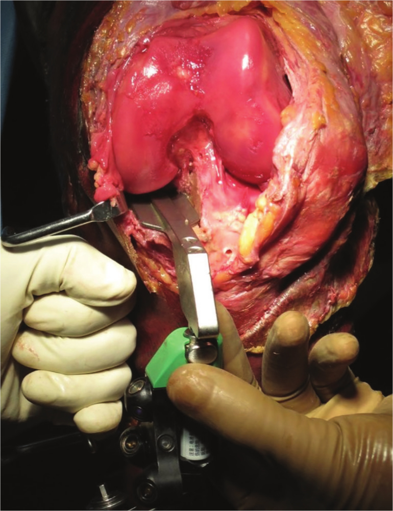
Fig. 1
Clinical photograph of the technique used for tibial cut assessment using navigation. The tibial rotation was assessed using a resection plane probe with navigation tracker attached, placed against the vertical sagittal cut. Patella has been subluxed laterally to demonstrate the use of the probe. During the study all assessments were carried out with the patella in an anatomical position.
Surgical precision
The amount of bone removed from the posterior femoral condyle and thickness of the resected plateau was measured. In addition, postoperative radiographs were assessed for component position as per the set criteria.6
Kinematic analysis
Tibiofemoral Var-Val and internal-external (IR-ER) rotations over the range of knee flexion were recorded from 0° to 135° passively, avoiding any external moments. A paired analysis to calculate the change in kinematics from the native knee to the operated knee was conducted to account for the variability in knee kinematics across the cadaveric specimens. The absolute difference between the matched mean kinematic measure pre- and post-implantation was plotted as a ‘delta’ curve for both groups and compared (Figures 2a and 2b). The cumulative difference was calculated by adding the area under the curve to produce one ‘delta-sum’ value for each kinematic measure.7
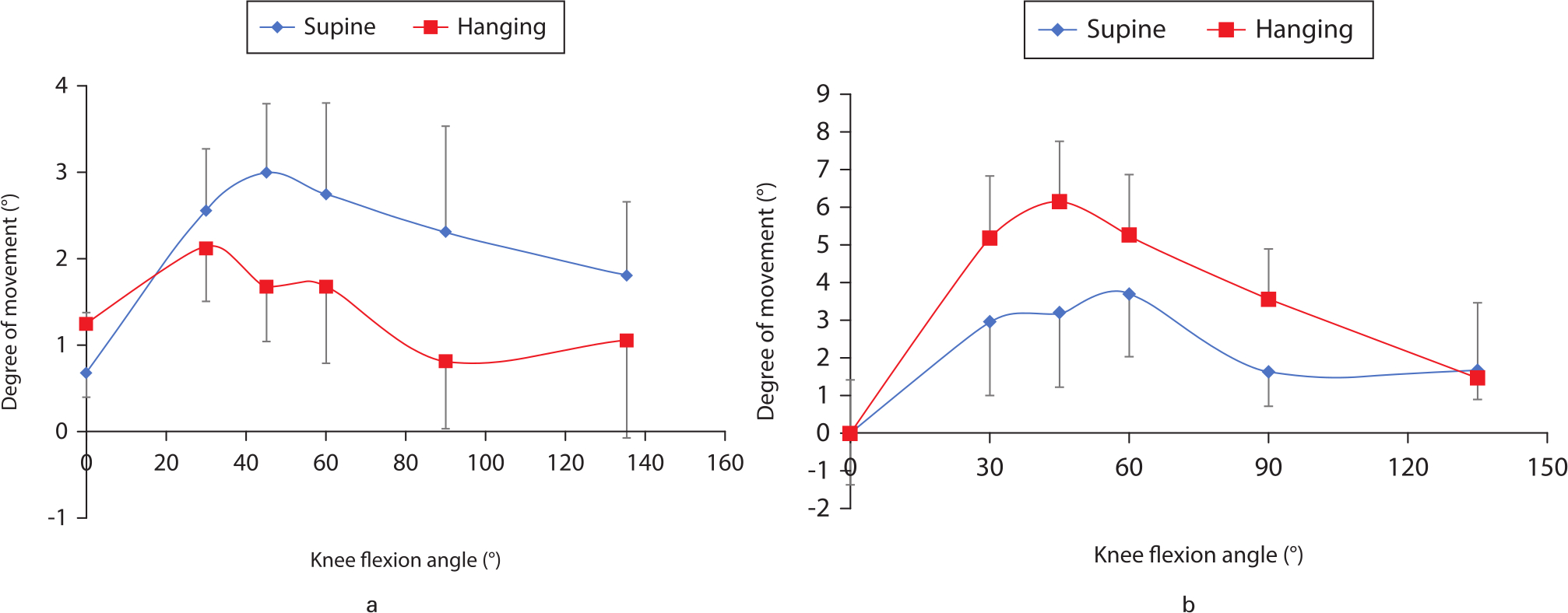
Fig. 2
Delta curves providing the absolute difference between the matched mean kinematic measure pre- and post-implantation for a) varus-valgus and b) internal-external rotation were quantified and plotted. The knee flexion angle (in degrees) is shown on the x-axis and the degree of movement in the a) coronal and b) axial plane shown on the y-axis.
Statistical analysis
The statistical analyses were performed using Excel 2010 software (Microsoft, Redmond, Washington, USA) and SPSS Version 11 (SPSS, Chicago, Illinois, USA). Continuous variables were compared using a two-tailed paired t-test with equal variance (p < 0.05). Multivariate analysis was done to find the difference between the two groups (SL and HL) based on the kinematic values for Var-Val as well as IRs and ERs observed at 0°, 30°, 45°, 60°, 90°, and 135° during the pre-surgery ROM test. The Wilcoxon signed-rank test was used to find the effectiveness of the surgical intervention between the two groups. Chi-squared test with Yate’s correction was used to compare the frequencies of outliers as per recommendations for component alignment.6 Statistical significance was set at p < 0.05.
Results
Surgical precision
The mean values for tibial coronal alignment, tibial rotation, and tibial slope were similar between the two groups (Table I). The variation in coronal alignment was within the acceptable range for OUKA for both groups. Six out of eight knees were malrotated (rotation outside the acceptable range of ± 5°) in the SL position, whereas this was seen in only one knee in Group 1 (HL) (Figure 3). This difference was statistically significant (p < 0.05).
Table I.
Navigation data analysis.
| Parameter | Position | Mean (SEM; range) | p-value* |
|---|---|---|---|
| Tibia coronal cut, ° † | Hanging leg | -1.3 (0.6; -4.5 to 0.5) | 0.219 |
| Supine leg | -2.1 (0.2; -3 to -1.5) | ||
| Posterior tibial slope, ° | Hanging leg | 6.3 (0 5; 4 to 8) | 0.165 |
| Supine leg | 5.1 (0.7; 3 to 8.5) | ||
| Tibial rotation, ° ‡ | Hanging leg | 1.6 (1.3; -5.5 to 5) | 0.625 |
| Supine leg | -0.3 (3.4; -13 to 11) |
-
*
Two-tailed paired t-test with equal variance.
-
†
A negative value signifies varus.
-
‡
A negative value signifies external rotation.
-
SEM, standard error of the mean.
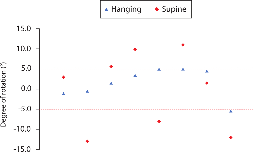
Fig. 3
Tibial rotation comparison. The distribution of tibial component rotation is shown for the two groups of knees. Rotation is represented along the y-axis with negative values representing external rotation and positive values representing internal rotation. There were significantly more outliers for tibial rotation outside the acceptable range of ± 5° in the supine leg position (n = 6) compared to those in the hanging leg position (n = 1).
Thickness of resected bones
The thickness of resected bone from the tibia and posterior femoral condyle was similar between the two groups (Table II).
Table II.
Bone measurement.
| Parameter | Position | Mean (SEM; range) | p-value* |
|---|---|---|---|
| Tibia biscuit thickness, mm (central) | Hanging leg | 5.7 (0.4; 3 to 7) | 0.436 |
| Supine leg | 6.3 (0.7; 3 to 9) | ||
| Posterior femur thickness, mm | Hanging leg | 3.5 (0.5; 2 to 5) | 0.400 |
| Supine leg | 3.9 (0.1; 3.5 to 4) |
-
*
Two-tailed paired t-test with equal variance.
-
SEM, standard error of the mean.
Implant positioning on radiographs
Radiographs of each knee were taken as per the Oxford protocol6 after implantation of trial components and the findings are provided in Table III. The mean femoral component alignment was similar between the two groups. There were three knees in the SL position and one knee in the HL position in which femoral component was neutral or extended. The difference between the two groups was not significant. On anteroposterior radiograph, Group 1 had three medial underhangs of the tibial component while Group 2 had two overhangs and two underhangs. One knee in Group 2 had a 3 mm overhang. While two knees in Group 1 had posterior underhang of tibial component, there were three posterior overhangs in Group 2 although none were significant.
Table III.
Radiological analysis by Oxford protocol.6
| Parameter | Position | Mean (SEM; range) | p-value* |
|---|---|---|---|
| Femur flexion,° | Hanging leg | -4.1 (1.3; -9 to 3) | 0.748 |
| Supine leg | -3.3 (2.4; -14 to 4) | ||
| Medial underhang or overhang | Hanging leg | 3× Underhang (1 mm, 1 mm, 2 mm) | N/A |
| Supine leg | 2× Overhang (1 × 3 mm), 2× Underhang (1 mm) | ||
| Posterior underhang or overhang | Hanging leg | 2× Underhang (2 mm) | N/A |
| Supine leg | 3× Overhang (2 × 2 mm, 1 × 1 mm) |
-
*
Two-tailed paired t-test with equal variance.
-
†
A negative value signifies extension of the femoral component.
-
N/A, not applicable; SEM, standard error of the mean.
Navigation kinematic data
Preoperative and postoperative kinematics were similar for both the groups. Area under the curve analysis was conducted to analyze the differences between the pre- and post-surgery kinematics mean values across the entire ROM of the two groups (IRER and Var-Val). The knees in Group 1 showed smaller differences as compared to Group 2 between the pre- and post-surgery conditions for both Var-Val and rotational kinematics (Figure 4), although the difference was not significant.
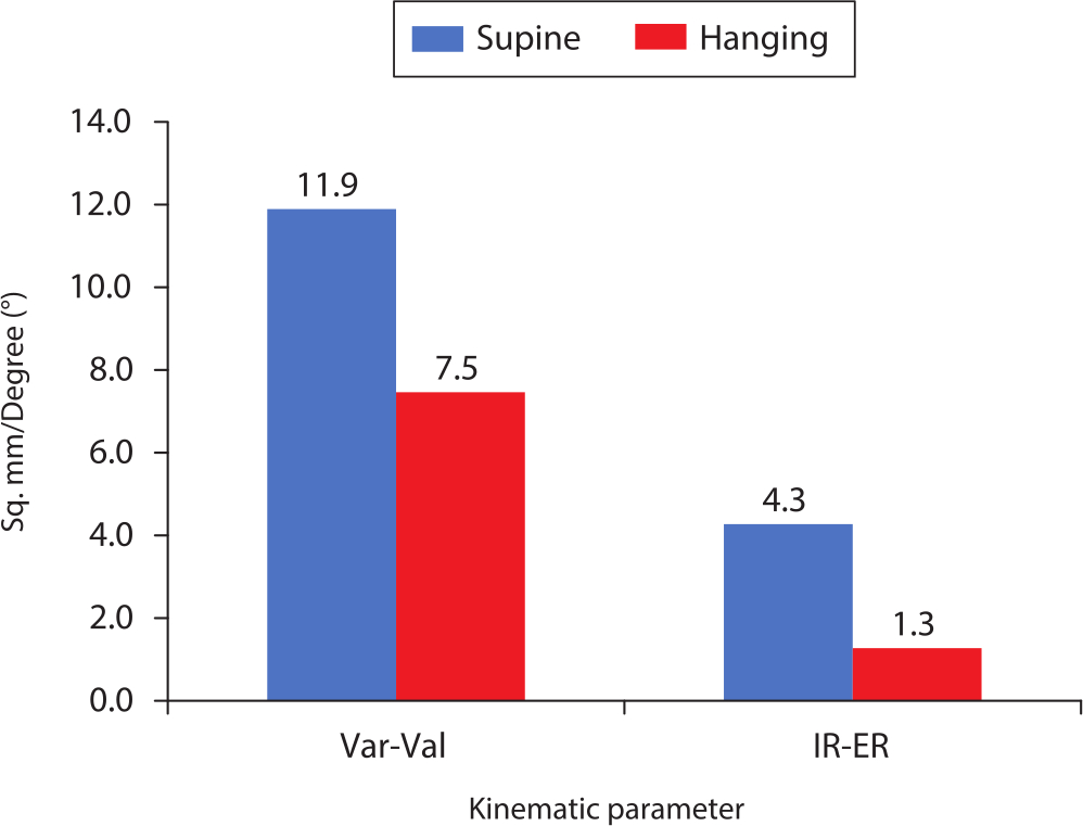
Fig. 4
Area under the curve analysis was used to analyze the differences between the pre- and post-surgery kinematics mean values across the entire range of motion of the two groups. The knees in the hanging leg group showed much smaller differences compared to those in the supine leg group for both varus-valgus and rotational kinematics, as seen by the height of the bar on the y-axis. IR-ER, internal-external rotation; Var-Val, varus-valgus.
Discussion
This is the first study to compare OUKA component placement in HL versus SL. Although most of the parameters assessed were similar between the two groups, the risk of tibial malrotation was significantly higher in the SL position. Similarly, the risk of getting femoral component extended was higher in the SL position although the difference between the two groups was not statistically significant.
The OUKA has been reported to have excellent survivorship and functional outcomes at the hands of designer and non-designer surgeons.8,9 Accurate positioning of the implant is imperative for good clinical outcome and longevity. In a designer series for OUKA, Gulati et al10 showed that a femoral malalignment of 10° and a tibial malalignment of 5° was compatible with good clinical and radiological outcomes. Other authors have shown that medial overhang of 3 mm or less did not compromise function.11 In a study on the impact of different tibial resections on tibial strain in a composite model, the most balanced strain response was seen with minimal distal resection, maximum lateralized placement, a neutral rotation with respect to the medial spine, and a 3° posterior slope.12
The sagittal tibial cut determines tibial component rotation and is the first bone cut performed in OUKA, being completely surgeon-dependent with only anatomy and visuospatial orientation as a guide. The knees in the HL group were better balanced, as seen in smaller differences between pre- and postoperative values for both Var-Val and IRs-ERs across the entire ROM. The area under the curve analysis assessed the differences between the pre- and post-surgery knee kinematics mean values across the entire ROM of the two groups. It showed significantly smaller values in the HL group, implying better restoration of kinematics post-implantation with respect to native normal knees. The aim of OUKA is to restore pre-disease native knee alignment and kinematics. This makes for a compelling case to perform OUKA in the recommended position of suspending the thigh in stirrups with the leg hanging freely.
The tibial sagittal cut determines component rotation in any design of medial UKA and in the absence of fixed landmarks for reference and is also the most imprecise bone resection. This cut was found to be more reproducible in the knees in the HL group and this would imply that the tibia component rotation would be better in these knees as well. The rotation of the tibial component in this study has been measured with respect to the transverse tibial axis because this was the only option available with the OrthoMap Precision Knee Navigation System. Campbell et al13 were perhaps the first to provide evidence of wide variability tibial component rotation in UKA on CT scan. Servien et al14 used the posterior tibial cortical rims as reference for rotation as described by Yoshioka et al15 in their CT study of fixed bearing UKA design performed in SL, and found that the mean rotation direction of the component was external with a large standard deviation.14,15 This finding was corroborated in another CT study of fixed bearing UKA, where the component was externally rotated by a mean of 11.9° (-1° to 32°). The functional scores were better in patients with lesser degrees of ER.16 Liow et al17 studied a fixed bearing design and concluded that greater than 3° of rotational malalignment on either side causes deterioration of functional scores.17 Kamenaga et al18 have studied the relationship between tibial component rotation on CT scan and functional outcome in OUKA, and reported a trend towards poorer outcome when the tibial component is placed in greater ER.18 The tibial bearing in the OUKA is fully congruous with the femoral component and slides posteriorly with flexion. When the femur component is placed laterally, the bearing moves in contact along the vertical wall of the tibial implant.19 Excessive ER will cause impact of the polyethylene bearing with the tibial lateral wall in flexion, with a theoretical risk of dislocation or reduced ROM and/or tibial loosening. Further, posteromedial overhang is possible with excessive ER when the component size selected aims to maximize coverage, and this has been reported as a cause of pain due to snapping of pes tendons.20 The tibial rotation of knees in the HL group was closer to neutral with lesser deviation compared to the SL group. In addition, in 75% of cases tibial rotation was outside the recommended range with three in excessive IR and three in excessive ER. This improved accuracy could be due to the foot and leg hanging freely and thereby opting for the natural position.
The other suggested advantage of the HL position for OUKA has been better assessment of ligament balance. There is no consensus on what constitutes a well-balanced UKA due to a paucity of clinical and biomechanical data.21 It has been proven in a cadaveric model that mobile bearing UKA leads to better restoration of kinematics in the unloaded state. Also, the presence of a mobile insert is likely to be beneficial during passive and squatting motion by preventing abnormal posterior translation of the medial femoral compartment.22 In another cadaveric study, Heyse et al21 underlined the importance of optimal balancing. They recommended against over-stuffing the joint as this led to larger kinematic changes compared to the native condition and caused excess strain in the superficial medial collateral ligament. However, the lateral compartment pressure was not increased even in over-stuffed knees.21 In our study, balancing the knee in the HL position did restore kinematics, which was closer to the native knee on Var-Val and rotational testing on area under the curve analysis. It has been our experience that balancing the knee in flexion is more difficult in the SL position. This could cause over-stuffing of the joint and a valgus malalignment, both of which are detrimental for OUKA. It is interesting to note that the SL cohort tended to have one degree more valgus, suggesting that the assessment of flexion gap in a SL position was inaccurate by 1 mm. Some surgeons are likely to continue to use the SL position while performing UKA. In such cases, they should meticulously check the orientation of the vertical cut for the tibia, implant under- or overhang, and assessment of flexion gap.
There are certain scenarios where using the HL position for performing OUKA is difficult. Perhaps the commonest one is when performing simultaneous bilateral OUKAs. Single-stage bilateral OUKA is a safe surgery with excellent outcomes.23 Putting one leg in a stirrup while the other leg is on the operating table and then changing over the setup in between sides is one possible solution while performing bilateral UKA under the same anaesthetic. Another situation is in very obese patients where the thigh does not fit the stirrup. The SL is an alternative in these situations, but the surgeon must be wary of getting the tibia rotation wrong considering the higher chances of tibial malalignment. Need for intraoperative conversion from UKA to TKA is quite unusual and when needed it really does not add more than a minute or two to adjust the setup. Compromising the result of intended surgery for the remote possibility of conversion to TKA is an avoidable choice.
We acknowledge the limitations of this study including simplification and assumptions owing to the study design. The cadavers used in the study had healthy knees and the kinematics of an arthritic knee may differ from the healthy state. The kinematics were recorded in a passive state, open-chain knee extension. It is possible that the results may be different in other activities. However, previous studies have shown that it is better to assess movements of an unloaded knee rather than a loaded knee.24 The forces applied during activity are as infinitely variable as the uses to which the human limb is put, and the consequent patterns of movement of the loaded knee are also infinitely varied.13 Blankevoort et al25 noted that the basis for the understanding of the kinematics of the knee joint lies in the description of its passive motion characteristics. Passive motion is what the surgeon observes on the operating table with the patient under anaesthetic.
In conclusion, the only step in the implantation of OUKA which is not dependent on the standard instrumentation is the sagittal tibia cut, which determines the tibial component rotation. The HL position improves accuracy of this step compared to the SL position and this may be because it provides better visuospatial orientation of the hip and knee to the surgeon. However, it does not differ from SL-operated knees for other implantation parameters which are executed with jigs or guides. The HL position is better for replicating native kinematics of the knee as shown by area under the curve analysis. When performing this surgery in the SL, the surgeon should be careful when making the sagittal tibia cut, while checking balance in flexion and when sizing the tibial component.
References
1. Hamilton TW , Pandit HG , Jenkins C , et al. Evidence-Based Indications for Mobile-Bearing Unicompartmental Knee Arthroplasty in a Consecutive Cohort of Thousand Knees . J Arthroplasty . 2017 ; 32 ( 6 ): 1779 – 1785 . Crossref PubMed Google Scholar
2. Hamilton TW , Choudhary R , Jenkins C , et al. Lateral osteophytes do not represent a contraindication to medial unicompartmental knee arthroplasty: a 15-year follow-up . Knee Surg Sports Traumatol Arthrosc . 2017 ; 25 ( 3 ): 652 – 659 . Google Scholar
3. Hamilton TW , Pandit HG , Maurer DG , et al. Anterior knee pain and evidence of osteoarthritis of the patellofemoral joint should not be considered contraindications to mobile-bearing unicompartmental knee arthroplasty: a 15-year follow-up . Bone Joint J . 2017 ; 99-B ( 5 ): 632 – 639 . Google Scholar
4. Beckers L , Ooms D , Berger P , et al. Reduced bone activity in the native compartments after medial mobile-bearing unicompartmental knee arthroplasty. A prospective SPECT/CT study . Bone Joint J . 2019 ; 101-B ( 8 ): 915 – 921 . Crossref PubMed Google Scholar
5. Price AJ , Rees JL , Beard DJ , et al. Sagittal plane kinematics of a mobile-bearing unicompartmental knee arthroplasty at 10 years: a comparative in vivo fluoroscopic analysis . J Arthroplasty . 2004 ; 19 ( 5 ): 590 – 597 . Crossref PubMed Google Scholar
6. Goodfellow J , O’Connor J , Pandit H , Dodd C , Murray D . Unicompartmental Arthroplasty with the Oxford Knee . Vol 1 . Second ed . Oxford : Goodfellow Publishers , 2015 . Google Scholar
7. Patil S , Bunn A , Bugbee WD , Colwell CW Jr , D’Lima DD . Patient-Specific implants with custom cutting blocks better approximate natural knee kinematics than standard TKA without custom cutting blocks . Knee . 2015 ; 22 ( 6 ): 624 – 629 . Crossref PubMed Google Scholar
8. Mohammad HR , Strickland L , Hamilton TW , Murray DW . Long-term outcomes of over 8,000 medial Oxford Phase 3 Unicompartmental Knees-a systematic review . Acta Orthop . 2018 ; 89 ( 1 ): 101 – 107 . Crossref PubMed Google Scholar
9. Alnachoukati OK , Barrington JW , Berend KR , et al. Eight Hundred Twenty-Five Medial Mobile-Bearing Unicompartmental Knee Arthroplasties: The First 10-Year US Multi-Center Survival Analysis . J Arthroplasty . 2018 ; 33 ( 3 ): 677 – 683 . Google Scholar
10. Gulati A , Chau R , Simpson DJ , et al. Influence of component alignment on outcome for unicompartmental knee replacement . Knee . 2009 ; 16 ( 3 ): 196 – 199 . Crossref PubMed Google Scholar
11. Chau R , Gulati A , Pandit H , et al. Tibial component overhang following unicompartmental knee replacement—does it matter? Knee . 2009 ; 16 ( 5 ): 310 – 313 . Google Scholar
12. Small SR , Berend ME , Rogge RD , et al. Tibial loading after UKA: evaluation of tibial slope, resection depth, medial shift and component rotation . J Arthroplasty . 2013 ; 28 ( 9 Suppl ): 179 – 183 . Crossref PubMed Google Scholar
13. Campbell DG , Johnson LJ , West SC . Multiparameter quantitative computer-assisted tomography assessment of unicompartmental knee arthroplasties . ANZ J Surg . 2006 ; 76 ( 9 ): 782 – 787 . Crossref PubMed Google Scholar
14. Servien E , Fary C , Lustig S , et al. Tibial component rotation assessment using CT scan in medial and lateral unicompartmental knee arthroplasty . Orthop Traumatol Surg Res . 2011 ; 97 ( 3 ): 272 – 275 . Crossref PubMed Google Scholar
15. Yoshioka Y , Siu DW , Scudamore RA , Cooke TDV . Tibial anatomy and functional axes . J Orthop Res . 1989 ; 7 ( 1 ): 132 – 137 . Crossref PubMed Google Scholar
16. Iriberri I , Aragón JF . Alignment of the tibial component of the unicompartmental knee arthroplasty . assessed in the axial view by CT scan: does it influence the outcome? Knee . 2014 ; 21 ( 6 ): 1269 – 1274 . Crossref PubMed Google Scholar
17. Liow MHL , Tsai TY , Dimitriou D , Li G , Kwon YM . Does 3-Dimensional In Vivo Component Rotation Affect Clinical Outcomes in Unicompartmental Knee Arthroplasty? J Arthroplasty . 2016 ; 31 ( 10 ): 2167 – 2172 . Crossref PubMed Google Scholar
18. Kamenaga T , Hiranaka T , Kikuchi K , et al. Influence of tibial component rotation on short-term clinical outcomes in Oxford mobile-bearing unicompartmental knee arthroplasty . Knee . 2018 ; 25 ( 6 ): 1222 – 1230 . Crossref PubMed Google Scholar
19. Kawaguchi K , Inui H , Taketomi S , et al. Intraoperative mobile-bearing movement in Oxford unicompartmental knee arthroplasty . Knee Surg Sports Traumatol Arthrosc . 2019 ; 27 ( 7 ): 2211 – 2217 . Crossref PubMed Google Scholar
20. Inui H , Taketomi S , Yamagami R , Tahara K , Tanaka S . Snapping Pes Syndrome after Unicompartmental Knee Arthroplasty . Knee Surg Relat Res . 2016 ; 28 ( 2 ): 172 – 175 . Crossref PubMed Google Scholar
21. Heyse TJ , Slane J , Peersman G , et al. Balancing mobile-bearing unicondylar knee arthroplasty in vitro . Knee Surg Sports Traumatol Arthrosc . 2017 ; 25 ( 12 ): 3733 – 3740 . Crossref PubMed Google Scholar
22. Peersman G , Slane J , Vuylsteke P , et al. Kinematics of mobile-bearing unicompartmental knee arthroplasty compared to native: results from an in vitro study . Arch Orthop Trauma Surg . 2017 ; 137 ( 11 ): 1557 – 1563 . Crossref PubMed Google Scholar
23. Clavé A , Gauthier E , Nagra NS , et al. Single-stage bilateral medial Oxford Unicompartmental Knee Arthroplasty: A case-control study of perioperative blood loss, complications and functional results . Orthop Traumatol Surg Res . 2018 ; 104 ( 7 ): 943 – 947 . Crossref PubMed Google Scholar
24. Wilson DR , Feikes JD , Zavatsky AB , O'Connor JJ . The components of passive knee movement are coupled to flexion angle . J Biomech . 2000 ; 33 ( 4 ): 465 – 473 . Crossref PubMed Google Scholar
25. Blankevoort L , Huiskes R , de Lange A . The envelope of passive knee joint motion . J Biomech . 1988 ; 21 ( 9 ): 705 – 720 . Crossref PubMed Google Scholar
Author contributions
S. Tapasvi: Designed the study, Performed the experimental work, Wrote the manuscript.
A. Shekhar: Wrote the manuscript, Performed the experimental work.
S. Patil: Designed the study, Wrote the manuscript, Performed the statistical analysis.
H. Pandit: Designed the study, Wrote the manuscript.
Funding statement
The author or one or more of the authors have received or will receive benefits for personal or professional use from a commercial party related directly or indirectly to the subject of this article.
ICMJE COI statement
S. Tapasvi and A. Shekhar report institutional grants for procuring the cadavers and for travel and logistic support (paid to The Orthopaedic Speciality Clinic) from the Tapasvi Charitable and Medical Center, Pune, India, all related to this study.
S. Tapasvi reports personal consulting fees for fellowship support from Zimmer Biomet, related to this study. S. Tapasvi also reports personal fees from Arthrex, grants, personal fees, and non-financial support from Zimmer Biomet, personal fees from Smith & Nephew, personal fees from ConMed, and royalties from Jaypee Medical Publishers, New Delhi, all unrelated to this study.
H. Pandit reports consultancy fees for education and institutional support for research from Zimmer Biomet, DePuy Synthes, and GlaxoSmithKline; consultancy for education from Meril Life, Medacta, and Bristol-Myers Squibb; and consultancy fees from Kennedy’s law firm for medicolegal work carried out in relation to metal-on-metal hips; all unrelated to this study.
A. Shekhar reports meeting expenses for IASCON 2019 from Biotek, not related to this study.
Acknowledgements
The authors are thankful for the financial support received from Tapasvi Charitable and Medical Centre, Pune, India for the conduct of this study. We acknowledge the assistance received from Prashant Gorur, Sagar Kakatkar, and Savneet Singh in the study and Mrs. R. Thilagavathi (School of Public Health, SRMIST, Chennai, India) for the statistical analysis. Prof Pandit is a National Institute for Health Research (NIHR) Senior Investigator. The views expressed in this article are those of the author(s) and not necessarily those of the NIHR or the Department of Health and Social Care.
Ethical review statement
The letter of waiver was obtained from the local Institutional Review Board as this was a cadaveric experiment.
© 2020 Author(s) et al. This is an open-access article distributed under the terms of the Creative Commons Attribution Non-Commercial No Derivatives (CC BY-NC-ND 4.0) licence, which permits the copying and redistribution of the work only, and provided the original author and source are credited. See https://creativecommons.org/licenses/by-nc-nd/4.0/.
