


Abstract
Objectives
Cadaveric models of the shoulder evaluate discrete motion segments using the glenohumeral joint in isolation over a defined trajectory. The aim of this study was to design, manufacture and validate a robotic system to accurately create three-dimensional movement of the upper body and capture it using high-speed motion cameras.
Methods
In particular, we intended to use the robotic system to simulate the normal throwing motion in an intact cadaver. The robotic system consists of a lower frame (to move the torso) and an upper frame (to move an arm) using seven actuators. The actuators accurately reproduced planned trajectories. The marker setup used for motion capture was able to determine the six degrees of freedom of all involved joints during the planned motion of the end effector.
Results
The testing system demonstrated high precision and accuracy based on the expected versus observed displacements of individual axes. The maximum coefficient of variation for displacement of unloaded axes was less than 0.5% for all axes. The expected and observed actual displacements had a high level of correlation with coefficients of determination of 1.0 for all axes.
Conclusions
Given that this system can accurately simulate and track simple and complex motion, there is a new opportunity to study kinematics of the shoulder under normal and pathological conditions in a cadaveric shoulder model.
Article focus
The glenohumeral articulation has the largest range of movement of any joint in the human body but is susceptible to injury when subjected to high stress, an extreme range of motion or repetitive use.
Most cadaveric models of the shoulder allow for discrete motions using an isolated glenohumeral joint over a defined trajectory without considering the contribution of other shoulder joints, such as the scapulothoracic joint.
We hypothesised that the continuous motion of the glenohumeral and scapulothoracic joints of an intact cadaveric shoulder can be described with high precision and accuracy using a robotically controlled system.
Key messages
We have designed a system that manipulates the entire cadaveric torso while considering the relative motion of the thorax, scapula, clavicle and humerus in an automated and real-time setting, in order to assess the biomechanics of shoulder motion.
Clusters of markers on the thorax, scapula, clavicle and humerus enable the digital motion analysis system to provide comprehensive kinematic analysis of various patterns of movement.
This system is readily programmable to generate any real-time and continuous motion trajectory covering the shoulder range of motion and specific cases, such as simulated pitching.
Strengths and limitations
The uniqueness of the system stems from its ability to recreate motions trajectories based on existing data sets in a highly reproducible manner.
Application of this system in normal and pathological conditions of the shoulder will allow for a clearer understanding of their kinematics as well as their associated surgical and non-surgical treatment options.
As with any cadaver-based model, the data generated from this system concerns passive motion only.
Introduction
The glenohumeral articulation has the largest range of movement of any joint in the human body. However, as a consequence of this impressive capacity for motion, the shoulder is susceptible to injury when subjected to high stress, extreme ranges of movement or repetitive use.1 Athletes who participate in activities involving overhead action such as tennis, swimming, volleyball, football and baseball, are at increased risk for shoulder injuries. Several ex vivo2-5 and in vivo6,7 biomechanical studies have examined the kinematics of the shoulder during daily and sport-specific activities.2 While these investigations have shed light on the biomechanics of shoulder injuries, their methodologies warrant a closer examination.
Most cadaveric models of the shoulder allow for discrete motions using an isolated glenohumeral joint over a defined trajectory.8-10 without considering the contribution of other shoulder joints, such as the scapulothoracic joint. They have also studied shoulder kinematics in discrete motions by moving the arm from one point to another, neglecting the continuous nature of the movement while introducing measurement and positioning errors between sequential repetitions.
We hypothesised that the continuous movement of the glenohumeral and scapulothoracic joints of an intact cadaveric shoulder can be described with high precision and accuracy using a robotically controlled system. Therefore, the aim of this project was to design, manufacture and validate a robotic system to accurately create three-dimensional (3D) movement and capture it using high speed cameras. We also aimed to implement this system in an intact cadaveric model to simulate the motion of throwing.
Materials and Methods
Design and manufacture of the testing system
In order to simulate the normal range of movement and pitching motion of the shoulder, a robotic system consisting of a lower frame (moving the torso) and upper frame (moving the arm) was designed to provide linear and rotational motion along seven axes. The lower frame was able to linearly move the torso in 3D and around its long axis (Z) (along XTORSO, YTORSO, ZTORSO, around ZTORSO-θ) while the upper frame was able to linearly move in 3D the end point of the arm (along XHAND, YHAND, ZHAND) (Fig. 1). This setup allows for the free 3D linear motion of the hand and torso, in addition to the rotation of the torso about its long axis. The testing apparatus utilised high-voltage Parker stepper motors (Parker-Hannifin, Cleveland, Ohio) to affect positioning of the actuators and gearboxes in order to improve output (Table I).
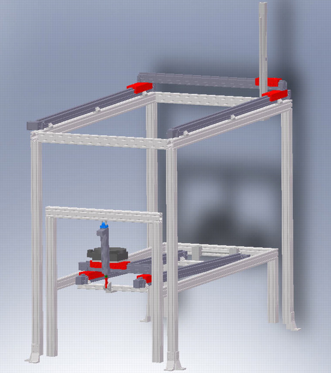
Fig. 1
Schematic view of the testing system, showing the torso and hand frames along with the reference system for both frames.
Table I
The robotic system actuators’ axes with their corresponding travel lengths and normal loads. The prime notation indicates a parallel track connected by a link shaft. ‘Actuator type’ includes both the actuator axis and Parker-Hannifin model. The Z-axis actuators act along the normal axis and thus do not have a normal load. The theta-axis actuator has 360° of rotational capability. All actuators were manufactured by Parker Automation (Cleveland, Ohio)
| Actuator model (Parker Automation) | Range of movement (mm) | Normal load (kg) |
|---|---|---|
| Upper (hand) | ||
| XX’-axis Dual ERV5 | 1832 | 114.8 |
| Y-axis AAD ERV | 1078 | 114.8 |
| Z-axis ET50 | 582 | N/A* |
| Lower (torso) | ||
| XX’-axis Dual ERV5 | 1513 | 114.8 |
| YY’-axis AAD ERV | 231 | 114.8 |
| Z-axis ET50 | 151 | N/A |
| Theta-Axis 200-series | 2 radians | 90.7 |
-
* N/A, not applicable
An adjustable posterior restraint was developed to generate the degree of external rotation required by the throwing motion (Fig. 2a). This device allows for proper positioning of the elbow during the late cocking phase of the throwing simulation and is easily manipulated to suit cadaveric specimens of heights between 1.60 m and 2.10 m.
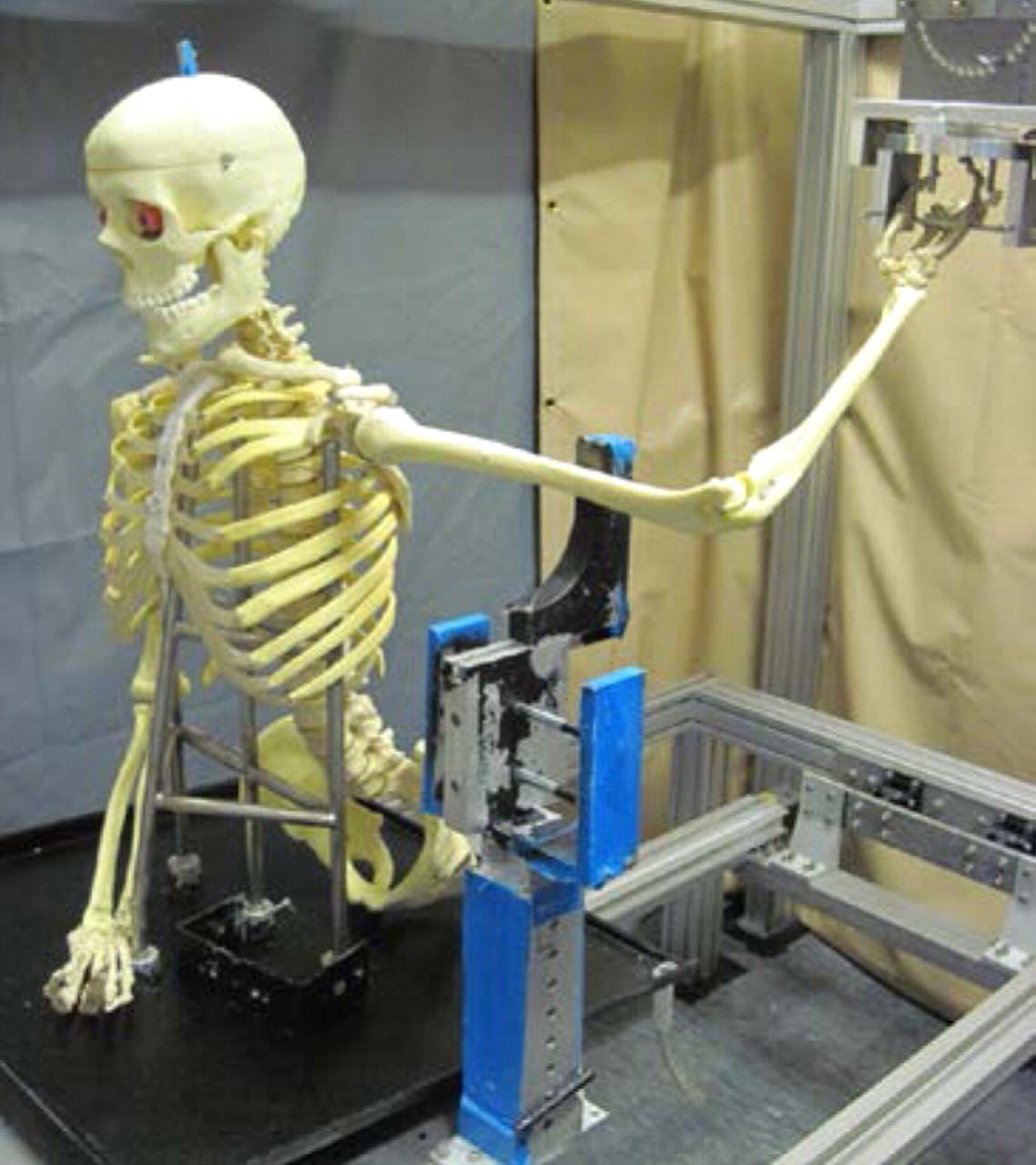
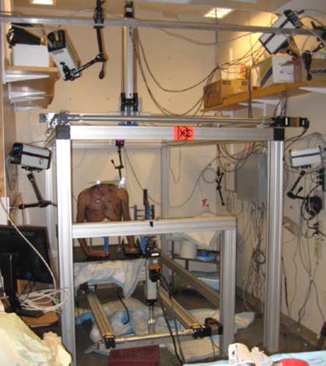
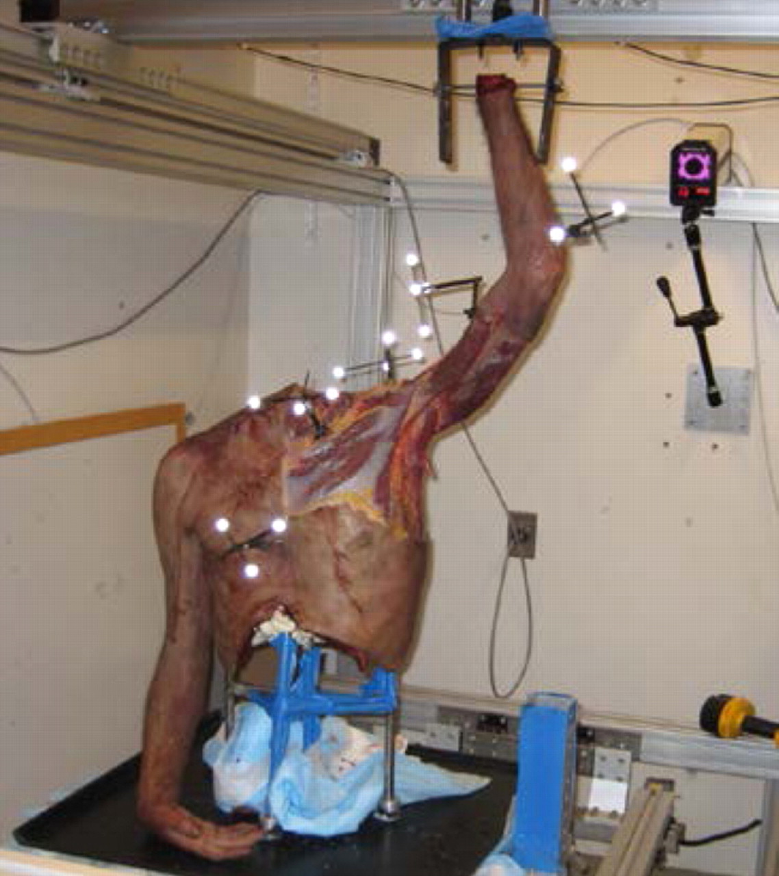
Figs. 2a - 2c
Photographs showing a) a saw-bone skeleton mounted onto the system with the arm fixed to the upper frame actuator, b) the testing apparatus with the cadaveric torso and the five-camera setup, with two cameras located on the side, two above, and one on the back wall behind the torso, and c) the placement of the five marker clusters on a human torso, each with three or four individual markers, on the sternum, clavicle, humerus, scapula and forearm.
A sensor system was implemented to monitor the motion of all axes and robotic drives. This feedback system facilitates communication between the computer and the testing apparatus. The system includes Hall Effect end of travel limits (SMC-1N) and home sensors (SMH-1N) (Parker-Hannifin). The home sensors define points of reference and create the coordinate system for the apparatus. The travel limits protect the specimen or the apparatus by defining the safe range of motion. An additional encoder system was included in the design to provide closed loop negative feedback for the stepper motors to ensure precision and accuracy. In this way, each axis was equipped with an E5 optical rotary encoder (US Digital, Vancouver, Washington) allowing for a resolution of 1000 counts per revolution.
Motion analysis component
Motion data were collected using five Qualisys ProReflex (Qualisys AB, Gothenburg, Sweden) high-speed cameras surrounding the testing apparatus (Fig. 2b). The cameras sampled the motion at 120 frames per second and were calibrated to discern motions as small as 0.5 mm. A passive retro-reflective cluster with three or four markers was pinned directly into the each of the bones of interest (humerus, clavicle, scapula and thorax (sternum)). Marker clusters were arranged to decrease the possibility of contact between the clusters during movement and to avoid overlap and mislabeling during the analysis (Fig. 2c). Anatomical landmarks selected by the International Society of Biomechanics11 were calibrated with respect to the bone-embedded marker clusters as described in Cappozzo et al.12 The centre of rotation of the glenohumeral joint in the scapular reference system was determined using the method described by Meskers et al.13 The centre of the glenohumeral joint was assumed to be coincident to the centre of the humeral head in a given reference posture (that of a hanging arm). Therefore, glenohumeral translation could be determined in the scapular reference system. All joint kinematics were described in the reference system of the relevant proximal segment.
Validation of robotic system
The precision and accuracy of the axes of the system was determined by comparing the measured displacement of each axis with the relevant expected displacement. The expected displacement was calculated based on the average number of revolutions of the actuator motor during three independent trials. To ensure accuracy over the entire range, each axis was tested from homing sensor (Parker SMC-1H) to 10%, 50% and 90% of the total possible distance. In order to demonstrate that loading the actuators during the experiment did not affect their validity, the lower frame was subjected to a 57 kg (125 lb) weight and validation process was repeated.
Validation of combined axes motion
The reference frame of the motion capture system was defined by the calibration object provided by the manufacturer. The reference frame of the robotic system coordinate system was aligned with the upper and lower frames. In order to minimise the potential effect of any misalignment between the reference frames, the magnitude of displacement was reported for a number of movements of the upper frame end effector. The magnitude of the displacement of the end effector of the upper frame through trajectories diagonally crossing the calibrated volume, as recorded by the robotic system, were compared with the displacement recorded by the camera system (four diagonal trajectories: A, B, C and D; Fig. 3). Similarly, two diagonal motions were used in the lower frame (E and F; Fig. 3). Each trajectory was tested three times. During validation, a separate retro-reflective marker cluster was placed on the hand and torso actuators (base plate) and their motion was captured.
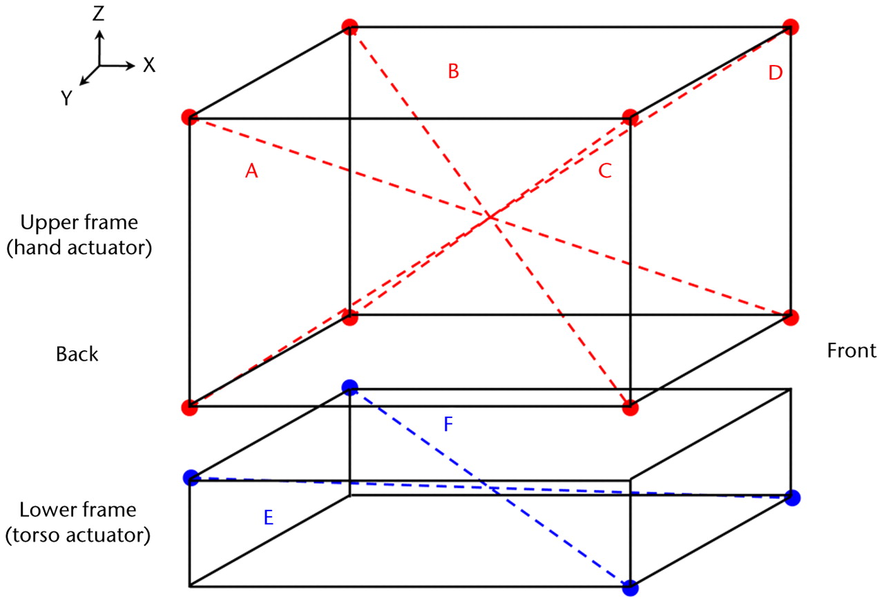
Fig. 3
Diagram showing the diagonal trajectories generated for the hand and torso actuators (Table IV).
Table IV
The precision and accuracy of the camera system to capture magnitude of displacement created for upper (hand actuator) and lower frames (torso actuators)
| Actual magnitude | Precision | Accuracy | |||||||||
|---|---|---|---|---|---|---|---|---|---|---|---|
| Diagonal | Expected magnitude | Mean (sd) | CV* (%) | ICC† | p-value | Error | Error (%) | CC‡ | p-value | ||
| Upper frame | |||||||||||
| A (mm) | 863.8 | 858.7 (0.0) | 0.0 | 1.0 | 0.001 | 5.2 | 0.0 | 1.0 | 0.001 | ||
| B (mm) | 863.8 | 863.1 (0.0) | 0.0 | 0.7 | 0.0 | 1.0 | 0.001 | ||||
| C (mm) | 863.8 | 865.2 (0.0) | 0.0 | 1.4 | 0.0 | 1.0 | 0.001 | ||||
| D (mm) | 863.8 | 868.2 (0.3) | 0.0 | 4.3 | 0.0 | 1.0 | 0.001 | ||||
| Lower frame | |||||||||||
| E (mm) | 1027.4 | 1022.8 (0.1) | 0.0 | 1.0 | 0.001 | 4.6 | 0.0 | 1.0 | 0.001 | ||
| F (mm) | 1027.4 | 1017.9 (0.6) | 0.0 | 9.5 | 0.0 | 1.0 | 0.001 | ||||
-
* CV, coefficient of variation † ICC, intraclass correlation coefficient ‡ CC, Pearson correlation coefficient
Cadaveric shoulder model
In order to simulate the pitching motion, motion data from professional Major League Baseball (MLB) pitchers (courtesy of Dr. G. Fleisig, American Sports Medicine Institute (ASMI)), were used to define the motion of the robotic system axes. The velocity of the simulated motion was slowed to 1/750th of the real-time throwing motion in order to ensure a smooth motion without damage to the cadaveric torso. As the majority of shoulder injuries happen during the initial phases of throwing motion,14,15 an abbreviated throwing motion (ATM) was defined with the data from the ASMI. It begins at maximal external rotation (late cocking) and continues through acceleration to ball release. The ‘mid-wrist’ coordinates were calculated by averaging the coordinates of the medial and lateral wrist markers in the throwing hand. The ‘mid-hip’ coordinates were calculated from the throwing and leading hip markers. In this model, the relative motion of the wrist to the body determines the shoulder‘s motion, the mid-wrist coordinates were re-calculated relative to the mid-hip. This treatment resulted in a described pattern of motion, with three degrees of freedom, which was then used to model the ATM motion using the hand actuator, while keeping the torso still.
The right and left shoulder of a 55-year-old fresh-frozen male cadaver (Medcure, Naples, Florida) were used for this study. A stainless steel frame was placed inside the thorax and secured with expandable polyurethane foam (Convenience Products, Fenton, Missouri) (Fig. 2a). The stainless steel frame was then mounted on the base plate. The hand was amputated at the wrist and a 5 mm Steinmann pin was drilled perpendicularly through the distal radius. An osteotomy of the distal ulna was performed to allow free rotation of the radius with respect to the proximal ulna, as performed in a Sauvé-Kapandji procedure in hand surgery.16 The specimen was then tested over the ATM, and its motion patterns were recorded.
Statistical analysis
The mean, standard deviation (sd) and coefficient of variation (CV) were calculated for the displacement of each axis in both loaded and unloaded conditions, and the expected (input data) travel for each actuator was compared with the directly measured observed (camera recorded data) travel to calculate the absolute and percentage error in movement. In order to determine precision, the intraclass correlation coefficient (ICC) for individual measurements was used for 10%, 50%, and 90% travel of each actuator. The Pearson correlation coefficient (CC) of the observed versus expected displacements for each actuator was used as a measure of accuracy. The same descriptive statistics were used for magnitudes of travel captured by the camera system. The ICC for individual measurement was used as a measure of precision, and the CC of the observed versus expected diagonal magnitude was used as a measure of accuracy.
The right and left shoulder of a cadaver were subjected to three trials of the ATM motion. Error bars representing the sd of glenohumeral translations and scapulothoracic rotations were reported.
The data analysis was performed using SPSS statistical software (version 17.0; SPSS Inc., Chicago, Illinois), and the level of statistical significance was set at p < 0.05.
Results
Robotic system
The testing system demonstrated high precision and accuracy based on the expected versus observed displacements of individual axes. The maximum CV for displacement of unloaded axes was less than 0.5% for all axes (Table II). Individual axes demonstrated displacement precision as evidenced by ICC values greater than 0.99 (p = 0.001) for three repeated trials of 10%, 50%, and 90% of the total travel. The expected and observed actual displacements had high level of correlation with coefficients of determination of 1 for all axes (p = 0.001). The absolute and percent errors in displacement of unloaded axes were 0 and less than 0.9%, respectively (Table II).
Table II
The precision and accuracy results for seven unloaded axes
| Actual displacement | Precision | Accuracy | |||||||||
|---|---|---|---|---|---|---|---|---|---|---|---|
| Axis (% axis length) | Expected displacement | Mean (sd) | CV* (%) | ICC† | p-value | Error | Error (%) | CC‡ | p-value | ||
| XTORSO (mm) | |||||||||||
| 10 | 145.0 | 145.0 (0.0) | 0.0 | 1.00 | < 0.001 | 0.0 | 0.0 | 1.00 | < 0.001 | ||
| 50 | 725.2 | 725.2 (0.0) | 0.0 | 0.0 | 0.0 | ||||||
| 90 | 1305.3 | 1305.4 (0.0) | 0.0 | 0.0 | 0.0 | ||||||
| YTORSO (mm) | |||||||||||
| 10 | 22.8 | 22.8 (0.0) | 0.0 | 1.00 | < 0.001 | 0.0 | 0.2 | 1.00 | < 0.001 | ||
| 50 | 114.2 | 114.2 (0.0) | 0.0 | 0.0 | 0.0 | ||||||
| 90 | 205.6 | 205.6 (0.0) | 0.0 | 0.0 | 0.0 | ||||||
| ZTORSO (mm) | |||||||||||
| 10 | -14.4 | -14.4 (0.0) | 0.0 | 1.00 | < 0.001 | 0.0 | 0.0 | 1.00 | < 0.001 | ||
| 50 | -72.4 | -72.4 (0.0) | 0.0 | 0.0 | 0.0 | ||||||
| 90 | -130.4 | -130.4 (0.0) | 0.0 | 0.0 | 0.0 | ||||||
| θTORSO (radians) | |||||||||||
| 10 | 0.2 | 0.2 (0.0) | 0.5 | 1.00 | < 0.001 | 0.0 | 0.5 | 1.00 | < 0.001 | ||
| 50 | 1.0 | 1.0 (0.0) | 0.2 | 0.0 | 0.9 | ||||||
| 90 | 1.8 | 1.8 (0.0) | 0.0 | 0.0 | 0.7 | ||||||
| XHAND (mm) | |||||||||||
| 10 | 179.1 | 179.1 (0.0) | 0.0 | 1.00 | < 0.001 | 0.0 | 0.0 | 1.00 | < 0.001 | ||
| 50 | 895.5 | 895.5 (0.0) | 0.0 | 0.0 | 0.0 | ||||||
| 90 | 1611.9 | 1611.9 (0.0) | 0.0 | 0.0 | 0.0 | ||||||
| YHAND (mm) | |||||||||||
| 10 | 107.4 | 107.4 (0.0) | 0.0 | 1.00 | < 0.001 | 0.0 | 0.0 | 1.00 | < 0.001 | ||
| 50 | 537.1 | 537.1 (0.0) | 0.0 | 0.0 | 0.0 | ||||||
| 90 | 966.9 | 966.9 (0.0) | 0.0 | 0.0 | 0.0 | ||||||
| ZHAND (mm) | |||||||||||
| 10 | 55.5 | 55.5 (0.0) | 0.0 | 1.00 | < 0.001 | 0.0 | 0.0 | 1.00 | < 0.001 | ||
| 50 | 277.8 | 277.8 (0.0) | 0.0 | 0.0 | 0.0 | ||||||
| 90 | 500.1 | 500.1 (0.0) | 0.0 | 0.0 | 0.0 | ||||||
-
* CV, coefficient of variation † ICC, intraclass correlation coefficient ‡ CC, Pearson correlation coefficient
Similar results were observed for loaded axes. The maximum CV values were less than 0.5% for all axes with high degree of precision presented by ICC values greater than 0.99 (p = 0.001) for three repeated trials (Table III). The absolute and percent errors in the displacement of loaded axes were less than 0.1 and 0.5%, respectively. The expected and observed displacements for all loaded axes reported correlation coefficients of 1 (p = 0.001).
Table III
The precision and accuracy results for four loaded axes
| Actual displacement | Precision | Accuracy | |||||||||
|---|---|---|---|---|---|---|---|---|---|---|---|
| Axis (% axis length) | Expected displacement | Mean (sd) | CV* (%) | ICC† | p-value | Error | Error (%) | CC‡ | p-value | ||
| XTORSO (mm) | |||||||||||
| 10 | 145.0 | 145.1 | 0.0 | 1.0 | < 0.001 | 0.0 | 0.0 | 1.00 | < 0.001 | ||
| 50 | 725.2 | 725.2 | 0.0 | 0.0 | 0.0 | ||||||
| 90 | 1305.4 | 1305.4 | 0.0 | 0.0 | 0.0 | ||||||
| YTORSO (mm) | |||||||||||
| 10 | 22.9 | 22.9 | 0.0 | 1.0 | < 0.001 | 0.0 | 0.1 | 1.00 | < 0.001 | ||
| 50 | 114.3 | 114.3 | 0.0 | 0.0 | 0.0 | ||||||
| 90 | 205.7 | 205.7 | 0.0 | 0.0 | 0.0 | ||||||
| ZTORSO (mm) | |||||||||||
| 10 | -14.5 | -14.5 | 0.0 | 1.0 | < 0.001 | 0.0 | 0.0 | 1.00 | 0.001 | ||
| 50 | -72.5 | -72.5 | 0.0 | 0.0 | 0.0 | ||||||
| 90 | -130.4 | -130.5 | 0.0 | 0.1 | 0.0 | ||||||
| θTORSO (radians) | |||||||||||
| 10 | 0.2 | 0.2 | 0.5 | 1.0 | < 0.001 | 0.0 | 0.5 | 1.00 | < 0.001 | ||
| 50 | 1.0 | 1.0 | 0.1 | 0.0 | 0.5 | ||||||
| 90 | 1.8 | 1.8 | 0.2 | 0.0 | 0.5 | ||||||
-
* CV, coefficient of variation † ICC, intraclass correlation coefficient ‡ CC, Pearson correlation coefficient
Combined axes motion
The diagonal motion was reproducibly captured by the high speed cameras showing a maximum standard deviation of 0.6 mm between the trials, in any direction (Table IV). The camera-based measurement of the six diagonal motions (four from the upper frame and two from the lower frame) showed high precision and accuracy. The absolute differences between robotic system and motion capture system estimates in observed magnitude of diagonal trajectories were a mean of 2.9 mm (sd 2.2) for the upper frame and 7.0 mm (sd 4.0) for the lower frame.
Cadaveric shoulder model
The sd of the ATM motion was < 0.2 mm. The precision of the camera system in capturing three trials was very high with an ICC of 1 (p < 0.001). The observed and expected ATM magnitudes highly correlated with a correlation coefficient of 0.99 (p < 0.001). The absolute error in observed ATM magnitude was a mean of 3.9 mm, corresponding to a relative error of 0.8%. The glenohumeral (GH) translations and scapulothoracic (ST) rotations in the planes of X, Y and Z during ATM motion were determined for the right and left shoulders (Fig. 4). The maximum sdof the GH translations along the three axes were 2.2 mm, 3.4 mm and 1.7 mm, respectively, while the maximum sd of the ST rotations around the three axes were 0.9°, 1.2° and 0.7°, respectively.
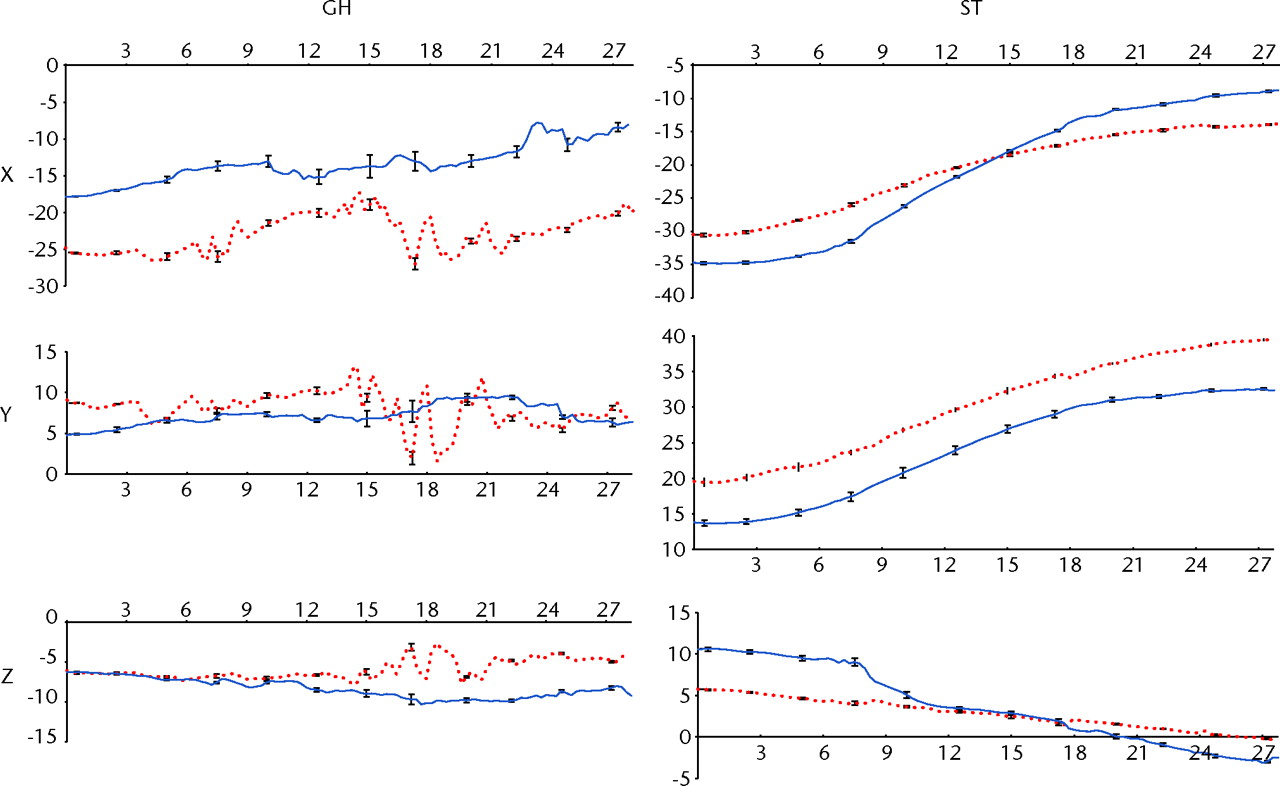
Fig. 4
Graphs showing the glenohumeral (GH) translation (in mm) and scapulothoracic (ST) rotations (in °) for the right and left shoulder (red and blue, respectively) in the cadaveric shoulder model, versus time (in seconds). The GH translation is reported in the scapular reference system and ST rotation is reported in the thoracic reference system. Error bars showing the standard deviation are also reported for instants of time.
In addition, the position of the scapula relative to the thorax, and the centre or rotation of the GH joint relative to the hanging arm in neutral position, was determined with high precision throughout the ATM. The scapula was retracted and externally rotated in the beginning of ATM. During the ATM, the scapula moved to a more protracted position as it tilted forward and rotated internally. At the start of the ATM, the head of the humerus was in a more posterior, lateral and inferior position relative to the hanging arm reference posture. As the arm progressed through the ATM, the humerus head translated anteriorly while the other translations were negligible.
Discussion
The novel robotic system presented in this study is able to generate motion with high precision and accuracy for both basic and complex shoulder motions that can be effectively measured with the motion capture system. This apparatus allows for testing of an intact cadaveric shoulder model performing an ATM. In doing so, the motions of the GH and ST joints can be determined accurately and precisely based on the 3D coordinates of clusters of markers attached to the bones and calibrated anatomical markers.
This programmable and fully automated system is capable of testing the entire cadaver torso with continuous data collection. As a model of shoulder function, it includes the relative motion of the thorax, scapula, clavicle and humerus. The uniqueness of the system stems from its ability to recreate motions trajectories based on existing data sets in a highly reproducible manner.
The minor discrepancy between camera system measurements and expected magnitudes (i.e. trajectory lengths) can be explained by a slight misalignment between upper and lower reference frames and minor variations between programmed and actual velocities.
As is the case with any cadaveric study, this system provides details on passive shoulder motion, where the contribution of active musculature cannot be reproduced.
In conclusion, this robotic system has been designed, manufactured and implemented to precisely and accurately recreate both simple and complex motions of the shoulder. Application of this system in normal and pathologic conditions of the shoulder will allow for a clearer understanding of their kinematics as well as their associated surgical and non-surgical treatment options. With this apparatus, it is possible to evaluate the effect of scapular dysfunction and rotator cuff pathology on both glenohumeral and scapulothroracic kinematics. Additionally, the impact of scapular winging, labral lesions, lesions of the long head of the biceps, clavicle fractures and rotator cuff tears on glenohumeral translations can be studied using this approach. For patients, this system promises a better understanding of the disease state as well as the intervention employed in their treatment.
The authors would also like to acknowledge the Scientific Instrumentation Facility at Boston University's Department of Physics for manufacturing key components of the system, and Mr Z. Darasz from Axis New England for providing excellent support with the system actuators and controllers.
1 Abrams GD , SafranMR. Diagnosis and management of superior labrum anterior posterior lesions in overhead athletes. Br J Sports Med2010;44:311–318.CrossrefPubMed Google Scholar
2 Yokoi K , ShihLC, KobayashiR, et al.Serum amyloid A as a tumor marker in sera of nude mice with orthotopic human pancreatic cancer and in plasma of patients with pancreatic cancer. Int J Oncol2005;27:1361–1369.PubMed Google Scholar
3 Yokoi K , ThakerPH, YaziciS, et al.Dual inhibition of epidermal growth factor receptor and vascular endothelial growth factor receptor phosphorylation by AEE788 reduces growth and metastasis of human colon carcinoma in an orthotopic nude mouse model. Cancer Res2005;65:3716–3725.CrossrefPubMed Google Scholar
4 Koomen JM , ShihLN, CoombesKR, et al.Plasma protein profiling for diagnosis of pancreatic cancer reveals the presence of host response proteins. Clin Cancer Res2005;11:1110–1118.PubMed Google Scholar
5 Cheng H , LangleyRR, WuQ, et al.Construction of a novel constitutively active chimeric EGFR to identify new targets for therapy. Neoplasia2005;7:1065–1072.CrossrefPubMed Google Scholar
6 Fidler IJ . Blockade of the TGF-beta superfamily by Smad7: breaking a link in the metastatic chain. J Natl Cancer Inst2005;97:1714–1715.CrossrefPubMed Google Scholar
7 Yokoi K , SasakiT, BucanaCD, et al.Simultaneous inhibition of EGFR, VEGFR, and platelet-derived growth factor receptor signaling combined with gemcitabine produces therapy of human pancreatic carcinoma and prolongs survival in an orthotopic nude mouse model. Cancer Res2005;65:10371–10380.CrossrefPubMed Google Scholar
8 Zuckerman JD , LeblancJM, ChouekaJ, KummerF. The effect of arm position and capsular release on rotator cuff repair: a biomechanical study. J Bone Joint Surg [Br]1991;73-B:402–405. Google Scholar
9 Hatakeyama Y , ItoiE, PradhanRL, UrayamaM, SatoK. Effect of arm elevation and rotation on the strain in the repaired rotator cuff tendon: a cadaveric study. Am J Sports Med2001;29:788–794. Google Scholar
10 McClure PW , MichenerLA, SennettBJ, KardunaAR. Direct 3-dimensional measurement of scapular kinematics during dynamic movements in vivo. J Shoulder Elbow Surg2001;10:269–277.CrossrefPubMed Google Scholar
11 Wu G , van der HelmFC, VeegerHE, et al.ISB recommendation on definitions of joint coordinate systems of various joints for the reporting of human joint motion. Part II: shoulder, elbow, wrist and hand. J Biomech2005;38:981–992. Google Scholar
12 Cappozzo A , CataniF, Della CroceU, LeardiniA. Position and orientation in space of bones during movement: anatomical frame definition and determination. Clin Biomech (Bristol, Avon)1995;10:171–178.CrossrefPubMed Google Scholar
13 Meskers CG , van der HelmFC, RozendaalLA, RozingPM. In vivo estimation of the glenohumeral joint rotation center from scapular bony landmarks by linear regression. J Biomech1998;31:93–96.CrossrefPubMed Google Scholar
14 Sabick MB , TorryMR, KimYK, HawkinsRJ. Humeral torque in professional baseball pitchers. Am J Sports Med2004;32:892–898.CrossrefPubMed Google Scholar
15 Gainor BJ , PiotrowskiG, PuhlJ, AllenWC, HagenR. The throw: biomechanics and acute injury. Am J Sports Med1980;8:114–118.CrossrefPubMed Google Scholar
16 Sauvé L, Kapandji M. Nouvelle technique de traitement chirurgical des luxations récidivantes isolées de l'extrémité inférieure du cubitus. J Chir 1936;47:589–594 (in French). Google Scholar
Funding statement:
The authors would like to acknowledge the Medical Advisory Committee for Major League Baseball (AN and AJR) and the Department of Orthopaedic Surgery at the Beth Israel Deaconess Medical Center for funding this project. The authors gratefully acknowledge the Swiss National Science Foundation SNF and the Swiss Society of Orthopaedic Surgery and Traunmatology for providing financial support to Dr C. Rosso and Dr A. Müller to work on this project. Dr C. Rossi and Dr A. Mueller are also affiliated with the Orthopaedic Department, University Hospital Basel, Basel, Switzerland.
Author contributions:
V. Entezari: Study design, Implementation, Paper writing
B. L. Trechsel: Design and implementation
W. A. Dow: Design and implementation
S. K. Stanton: Design and implementation
C. Rosso: Data collection and analysis, Paper writing
A. Müller: Data collection and analysis, Paper writing
B. McKenzie: Data collection and analysis, Paper writing
V. Vartanians: Design and implementation
A. Nazarian: Study design, Data analysis, Paper writing
J. P. DeAngelis: Study design, Paper writing
A. J. Ramappa: Study design, Paper writing
A. Cereatti: Data collection and analysis, Paper writing
U. Della Croce: Data collection and analysis, Paper writing
ICMJE Conflict of Interest:
None declared
©2012 British Editorial Society of Bone and Joint Surgery. This is an open-access article distributed under the terms of the Creative Commons Attributions licence, which permits unrestricted use, distribution, and reproduction in any medium, but not for commercial gain, provided the original author and source are credited.
