


Abstract
Anatomical total knee arthroplasty alignment versus conventional mechanical alignment; or a combination?
Introduction
Total knee arthroplasty (TKA) surgery faces a dilemma. The established method of alignment to the mechanical axis results in excellent implant longevity, but with less than ideal clinical functional and pain outcomes for some patients. A relatively recent development has been the concept of TKA implant positioning according to individual patient anatomy (also known as ‘kinematic’ alignment). There is evidence that anatomic individualised TKA implant positioning results in markedly improved functional outcomes. However, the methods published so far involve implant positioning that is not consistently aligned to the mechanical axis. Therefore, there is some justified concern that improved function is being achieved at the expense of compromised, long-term durability.
Conventional TKA creates resections according to the mechanical axis. Intra-operative releases and post-operative physiotherapy adapt the soft tissue to comply with the implant position and biomechanics. The outcome of this process can be variable. Anatomic individualised TKA ‘resurfaces’ the knee articulation so that the implants are in congruity with soft-tissue biomechanics at the onset. This means less need for soft tissue adaptation and less likelihood of stalled rehabilitation.
The rationale behind the concept of anatomic individualised TKA is becoming more widely accepted, and the ‘best of both worlds’ can be achieved (Table I).
Table I.
Anatomic individualised total knee arthroplasty: key points
| • Conventional TKA alignment results in good implant durability, but with limited functional outcome. Greater anatomical alignment improves outcome. |
| • Conventional TKA alignment makes several approximations and relies on soft tissue adaptation, which may contribute to its limitations. |
| • Anatomical alignment ‘resurfaces’ the knee and achieves better congruency between soft tissue and implant biomechanics, and hence an improved functional outcome. |
| • However, the methods for anatomical alignment previously described involve using symmetric implants to resurface an asymmetric femur. This results in oblique implant positioning, raising concerns that durability may be compromised. |
| • The salient features of anatomical alignment that correspond better with soft tissue biomechanics include: |
| ◦ Aligning to the natural coronal axis of the limb within a safe range, rather than the neutral mechanical axis |
| ◦ Aligning implants to the anatomical distal femoral axis of rotation |
| ◦ Observing the differing levels of the medial and lateral joint lines |
| ◦ Making allowances for cartilage wear in measuring resections |
| ◦ Maintaining the spatial relationship between lateral femoral condyle and patella |
| ◦ Reproducing the anatomical posterior femoral offset and tibial plateau sagittal slope |
| ◦ Overall, maintaining the spatial relationship between the femur, tibia and patella and hence minimising the requirement for soft tissue releases and post-operative adaptation |
| • An ideal mix of both considerations would combine stable implant positioning with the beneficial features of anatomical alignment. |
Background
Total knee arthroplasty is one of the most successful and widely-performed surgical procedures in the world. Annually, 80 000 cases are performed in England and Wales1 and The National Institute for Health and Care Excellence (NICE) considers interventions costing less than £20 000 per QALY to be cost-effective.2 A study by Dakin et al3 calculated TKA to cost £5 600 per QALY, which is well below this threshold; the same conclusion was reached in Scotland.4 Therefore, there is a justification for the increasing number of TKA performed. However, in the USA, over 700 000 TKA are performed annually, a figure that is expected to increase by 673% to 3.48 million annually by 2030.5 The overall health economic burden of TKA in all countries is enormous, placing further importance on the surgeons’ ability to perform the operation as well and with as little cost as possible. The success of the operation can be defined in terms of the durability of the implant and also the quality of the clinical outcome.
Measuring the outcome of TKA
Durability
The National Joint Registry of England and Wales (NJR)1 records a ten-year revision rate of less than 3% for the most commonly-used and best TKA implants aligned according to established conventional techniques. Aseptic loosening is an indication in 1.4/1000 patient years revisions; soft-tissue problems such as instability and stiffness are an indication in 0.73 and 0.39 revisions/1000 patient years respectively. Revisions for symptomatic TKA that have not failed are only carried out for extreme cases. The incidence of revisions for soft-tissue problems is likely to under-represent the prevalence of this type of symptomatic TKA, as revisions in this circumstance are known to have variable results and surgeons are widely hesitant to perform them.
Clinical outcome
This can be measured in terms of overall patient satisfaction and large-scale surveys in England and Wales,6 Canada,7 Sweden8 and the New Zealand Joint Registry9 have all produced similar findings of around 80% satisfaction. A more objective assessment of functional improvement can be made using a validated domain-specific scoring system such as the Oxford Knee Score (OKS). This is measured nationally in England and Wales10 and shows an overall improvement of 16 points at six months. This contrasts with a 20 point improvement for THA with the Oxford Hip Score (OHS). It must be remembered, however, that although the OHS and OKS are designed to be reliable and responsive, they are unlikely to be point-for-point comparable across the whole range.
Nam et al11 surveyed patients in the United States following TKA. They looked for the prevalence of a knee that felt ‘normal’ and found it to be 66%. There was no relationship between the type of implant or alignment method and the status of ‘normality’, with only one exception: the so-called ‘kinematic’ method of alignment. This correlates with significantly improved clinical outcomes following TKA with contemporary implants, described for ‘kinematic’ alignment by Dossett12 and Howell.13 Dossett showed a seven point OKS advantage for the ‘kinematic’ group over traditional alignment at one year. The minimum clinically important change when comparing groups of patients is five points.14 Thus, it appears that there is the potential to improve the clinical outcome of TKA. However, the method employed by Dossett and Howell is no longer available and it involved implanting the tibial component oblique to the mechanical axis, raising concerns over implant durability. Nonetheless, there remains a strong interest in reproducing these results by other means.
Biomechanical considerations
The knee joint, in common with other joints, can be considered as a composite of the hard articulation and the soft-tissue envelope, which function together as one biomechanical unit. In the native healthy joint, there is absolute congruency between the biomechanics of the hard articulation and the soft tissue envelope. Typically there is some laxity of the lateral soft tissue in flexion15 and tautness of most structures in full extension. If the hard articulation undergoes prosthetic arthroplasty, it is necessary to maintain the congruency between the articulation and the soft-tissue biomechanics for good function. Soft tissue placed under tension causes pain and stiffness (Fig. 1). Excessive laxity causes symptomatic instability16 and also instability-related pain.

Fig. 1
The tight knee arthroplasty: applying tension to musculoskeletal soft tissue causes pain.
The femur, tibia and patella have a complex dynamic spatial relationship with each other, maintained by the soft-tissue envelope, which imparts stability whilst permitting controlled motion. A well-functioning TKA would, therefore, resurface the joint without disturbing the spatial relationship between the bones of the joint, and hence without introducing excessive laxity or tension to the soft-tissue envelope.
Anatomical studies by Freeman17 Monk18 and Eckhoff19-21 allow a conceptual mechanical model of the knee to be described. Each femoral condyle has a particular radius, and the medial condyle is larger than the lateral in most subjects with individual unique variation. Knee flexion occurs around a single axis passing through the centres of both condyles (Fig. 2).

Fig. 2
Femoral-tibial articulation follows a circular path around the distal femoral rotation axis.
Given that the two condyles have different and unique radii, the axis is also in a unique position, which is not, therefore, parallel with the surfaces of the condyles (unless the patient happens to have femoral condyles of equal radii; Fig. 3). For the typical patient, the medial femoral condyle with a larger radius will articulate with a lower medial tibial plateau, relative to the lateral tibial plateau.
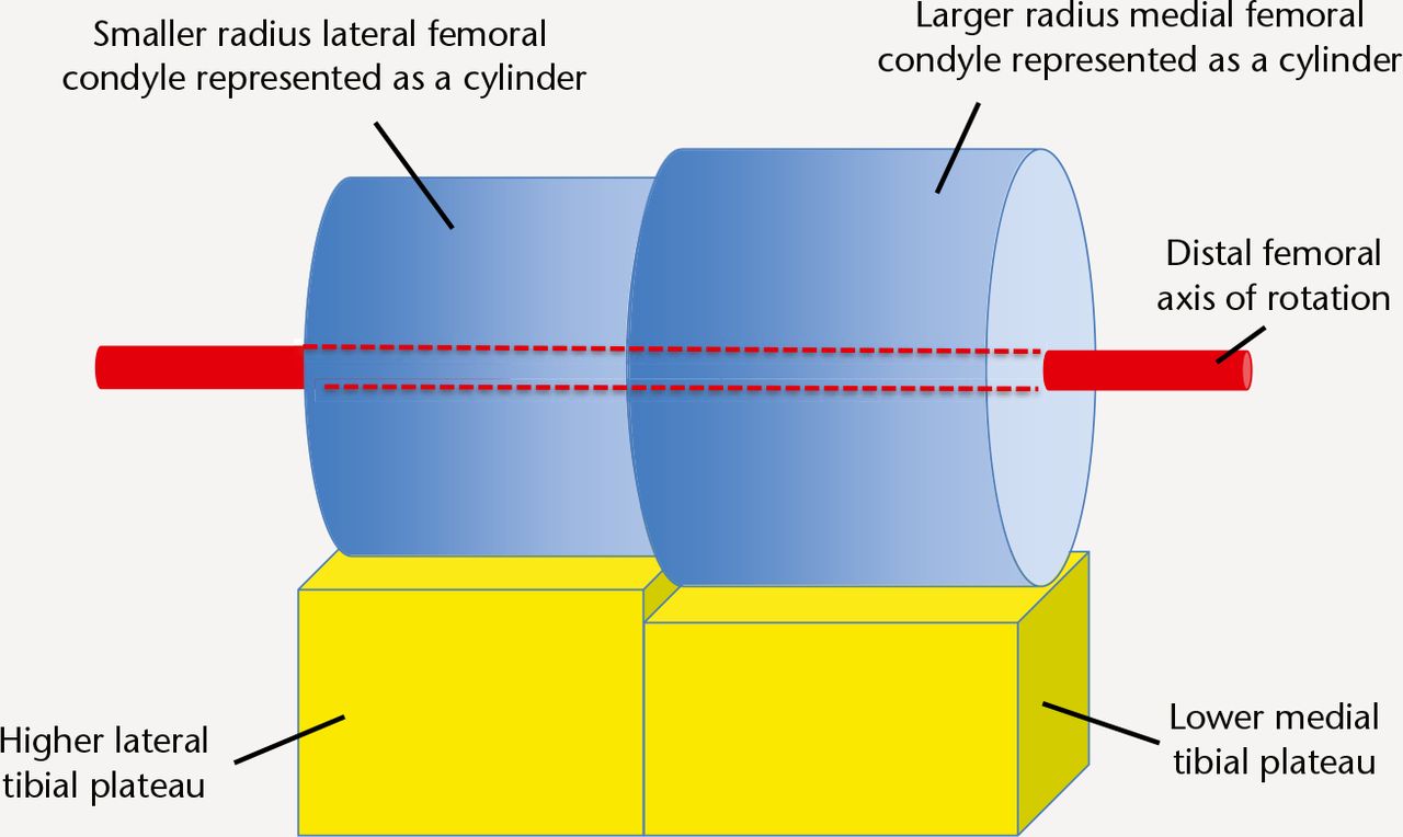
Fig. 3
Schematic representation of the natural femoral-tibial articulation. A unique single axis of rotation passes through the centres of both femoral condyles (not necessarily perpendicular to the mechanical axis of the limb or femur or tibia; it is only shown as such in this diagram for simplicity).
Komistek22 showed that knee rotation around a longitudinal axis during flexion is a product of differential rollback of the femoral condyles, and occurs around the medial compartment (the medial pivot principle). Echoff19-21 demonstrated that medial pivot rotation is still consistent with femoral condyles functioning as cylinders. Komistek23 also showed however that only half of TKAs exhibit medial pivot motion.
In extension the femoro-tibial articulation makes maximal contact at a point approximately one-third along the anterior-posterior axis of the tibial plateau (Fig. 4).

Fig. 4
In extension the femur articulates with the tibia at the 1/3 posterior position.
In 90° of flexion, the point of maximal contact rolls back to approximately two-thirds along (Fig. 5). The collateral ligaments maintain physiological tension in accordance to the spatial relationship between femur and tibia through this natural path of motion. If the sagittal posterior slope of the tibial plateau or the posterior offset of the femoral condyles were altered, the spatial relationship between the femur and tibia would change, affecting the soft tissue tension in flexion.24

Fig. 5
In flexion, the patella articulates with the distal aspect of the lateral femoral condyle and trochlea. Distalisation of the lateral femoral condyle exerts pressure against the patella and soft tissue envelope. The femur articulates with the tibia at the 2/3 posterior position. The posterior femoral offset is shown by the yellow arrow.
The spatial relationship between patella and lateral femoral condyle and motion of the patella-femoral joint follows another conceptual cylinder in the distal lateral femoral condyle and trochlea,18 also restrained by the soft-tissue envelope of the knee. The anatomical features of the knee that drive the biomechanics follow well-understood principles; however, the positions of the axes are unique to each knee.
The limb axis
Conventionally, a neutral mechanical axis of the limb has been described passing through the centres of the hip, knee and ankle25 (Macquet’s line) and traditionally TKA surgeons have sought to position the prosthesis perpendicular to this, with the aim being symmetrical and perpendicular implant-loading, with a mostly stable compressive force being applied during stance phase at the implant-bone interface (+/- cement) (Fig. 6). There are, however, some further considerations. Healthy subjects exhibit a unimodal distribution of lower limb alignment as a typical biological variable. The mean alignment of healthy knees is in fact about 2° of varus (more varus for men)26 with several degrees of variation. Even if the mechanical axis is described in the anatomical position, during gait the limb itself is loaded in a variety of angles, mostly varus (given that when patients walk, they tend to place the feet nearer to the midline than in the anatomical position). On the other hand, obesity (increasingly a feature of patients undergoing TKA) holds the thighs apart, imparting a more valgus posture. This variation means that the TKA implant is subjected to loading within several degrees either side of the neutral mechanical axis.
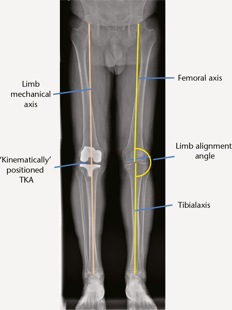
Fig. 6
The axes of the lower limb and a ‘kinematically’ positioned TKA, corresponding to the differing heights of the medial and lateral compartments but not perpendicular to the limb mechanical axis.
Constitutional malalignment as a risk factor for osteoarthritis and implant failure
It is a commonly-held belief that constitutional varus or valgus beyond a few degrees is a risk factor for the development of osteoarthritis (OA), and surgeons have sought to ‘correct’ alignment to the neutral mechanical axis, lest the implant succumb to the same fate. The evidence for this phenomenon is scant. Pathogenesis of OA is multifactorial, and meniscal tears earlier in life are a significant risk factor.
Parratte27 and others have studied the link between implant durability and limb alignment. They showed that contemporary TKA implant failure at 15 years is associated with alignment beyond 8° from neutral, but not smaller amounts of angulation. However, one needs to allow for the inaccuracy in instrumentation and measurement error (usually around 3°).
Limitations of conventional TKA technique
Limb alignment
Conventional TKA technique is directed at the ‘typical’ knee and makes certain assumptions concerning coronal limb alignment:
-
In extension, distal femoral and tibial resections are made perpendicular to the perceived neutral mechanical axis. It is assumed that this will produce a rectangular (i.e. balanced) extension gap. However this would only be the case if the patient truly had a neutral axis (which only a minority do) and the resections were accurate.
-
If the standard resections do not produce a rectangular extension gap, this is due to ligament contracture or stretching. This may sometimes be the case, but an alternative explanation is that the patient may simply have had a constitutional varus or valgus limb or there may be some inaccuracy in the resections.
-
Ligament releases are required to ‘match’ the soft tissue to the resections. In fact the surgeon is sometimes making unnecessary soft tissue releases in order to change the otherwise normal soft tissue to comply with any inaccuracy in the resections or to change an acceptable small degree of constitutional varus or valgus to comply with the resections.
Given that most limbs have a constitutional varus posture, conventionally the surgeon will make resections according to a neutral mechanical axis and release and lengthen the medial collateral ligament (MCL) in order to balance the knee in extension. However, the same release may unhelpfully impart imbalance in flexion, especially if a measured resection method is used for the flexion gap.
Conventional TKA joint line restoration
The tibial resection is usually measured from the less worn lateral compartment and is perpendicular to the tibial axis in the coronal plane. Most patients have a lateral compartment that is higher than the medial. Thus conventional technique resects less than implant thickness from the medial tibial plateau thereby raising the medial joint line with the implant (Fig. 7a). In effect the tibial implant is positioned according to the lateral compartment joint line.

Fig. 7
a) Conventional technique resects less than implant thickness from the medial tibial plateau, raising the medial joint line with the implant; b) the distal femoral resection is measured using jigs that rest against the more prominent medial femoral condyle; c) overlapping resections.
Meanwhile the distal femoral resection is measured using jigs that rest against the more prominent medial femoral condyle (Fig. 7b). Thus the resections overlap (Fig. 7c) and are also subject to individual anatomy and surface wear. Joint line restoration is therefore approximate. Restoration of the joint line directly correlates with function46 and is not optimal with conventional TKA technique.
The distal lateral femoral condyle resection is thinner than implant thickness and leads to distalisation of the lateral femoral condyle with the femoral implant [Fig. 8]. This imparts pressure against the patella in flexion and hence the lateral soft tissue. This can contribute to lateral soft tissue tension, pain and limitation to flexion (Fig. 9).
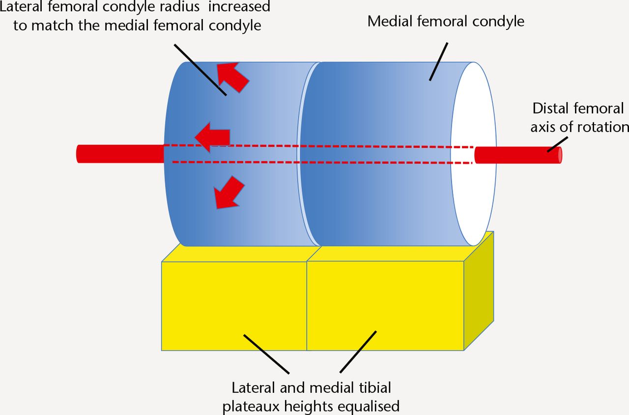
Fig. 8
Schematic representation of conventional TKA technique – The radius of the lateral femoral condyle is increased to match the medial femoral condyle. This can impart more tension on the patella and the soft tissue envelope.
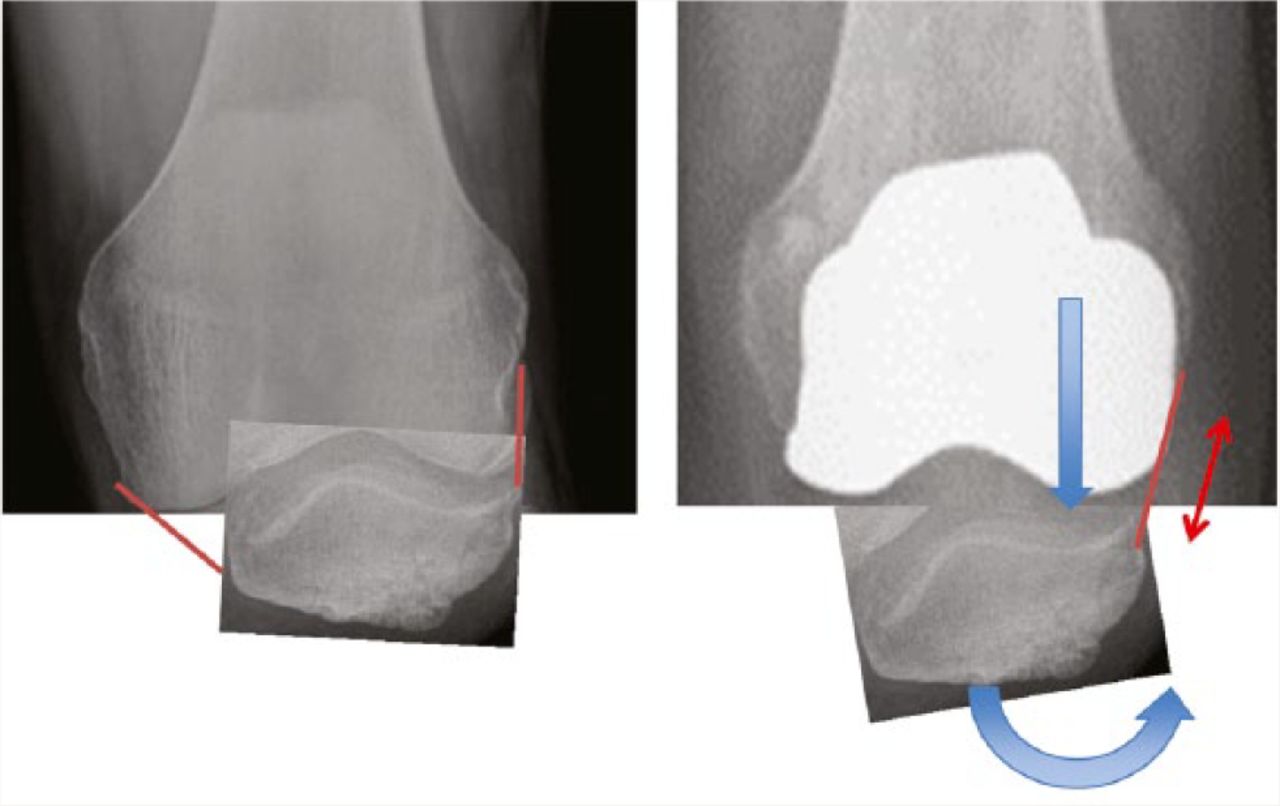
Fig. 9
Distalisation of the implant lateral femoral condyle exerts pressure against the patella.
Conventional TKA flexion gap
Typically patients have a lateral femoral joint line that is higher than the medial equivalent to 3° of angulation relative to the tibial axis. Having made a ‘flat’ tibial resection, the most commonly used conventional method (measured resection) introduces an arbitrary 3° of external rotation to the femoral component position, in order to compensate and achieve a balanced flexion gap. However, if the patient has a different coronal joint slope, the arbitrary 3° will not result in a balanced flexion gap (Fig. 10). Wear of the posterior femoral condyles also affects posterior referencing jigs as does medial or lateral release performed for the benefit of the extension gap. Balanced flexion gap resection is possible but when used in conjunction with otherwise standard conventional technique, there is no evidence to show an improved overall outcome.

Fig. 10
The larger radius medial femoral condyle articulates with the lower medial tibial plateau in extension (left) and flexion (right). A tibial resection perpendicular to the tibial axis (dotted line) resects less bone from the medial tibia. In flexion the femoral component is conventionally placed in 3° external rotation relative to the posterior femoral condyles in order to compensate, however, this is only accurate for the typical patient and not every patient as there is individual variation in the discrepancy between the joint level heights.
Conventional TKA tibial resection posterior slope
This is usually arbitrary and surgeons will either use the implant manufacturer’s recommended slope, or have their own preference. If the tibial resection that is made is less steep than the native anatomy, the size of the flexion gap is reduced and vice versa (Fig. 11).

Fig. 11
The flexion gap: the spatial relationship between femur and tibia in flexion is a product of the femoral AP size (including posterior femoral offset) and a matching tibial plateau height and posterior slope (green). If the tibial plateau is made more steep (red line) laxity results, less steep (blue line) results in tension.
If the posterior femoral resection is a measured resection and hence fixed, the soft tissue tension in flexion will not necessarily be optimal.
Computer navigation
This uses the same principles as the conventional TKA methods but imparts greater accuracy.28-30 It has not been shown to improve the functional outcome.31-33 This suggests that accuracy of resection alone will not improve functional outcomes.
Patient-specific instrumentation (PSI)
Used as an alternative method of achieving conventional alignment, these devices do not offer any benefit in terms of alignment or clinical outcome.34 A comprehensive review concluded that available evidence did not show any overall benefit at all with PSI.35
In summary
Conventional TKA alignment makes certain assumptions and approximations and does not reproduce natural knee anatomy or biomechanics as faithfully as could be achieved. It also relies on soft tissue releases and post-operative soft tissue adaptation, which can be unpredictable. We can hypothesise that these limit the average functional outcome and may produce poor outcomes for some patients especially patients with atypical anatomy, whom the usual ‘recipe’ does not suit.
The case for anatomical limb alignment
Resection angles can be individualised to the constitutional axis of the patient. Many surgeons already resect the tibia perpendicular to the tibial axis and then vary the distal femoral resection to ‘gap-balance’ the extension gap. Some authors make anatomical tibial and distal femoral resections.12,13 In both cases the tibial and femoral components are not necessarily aligned to the overall limb mechanical axis, however, the former method appears to have greater acceptability in review articles probably because there is evidence that excessive varus tibial component positioning is a risk factor for loosening.36
The limitations of this approach are as follows:
-
The surgeon is assuming that the soft tissue remains in its pre-disease state. In fact in the presence of even moderate acquired deformity, stretching or contracture of soft tissue may have occurred and soft tissue guided alignment may not reproduce pre-disease anatomy.
-
If aligning to the constitutional axis, some patients will have extreme alignment. This may result in TKA alignment outside an acceptable range. There would need to be a measure to ‘moderate’ and still make releases for outliers.
The case for anatomical implant positioning
The intention of anatomic implant positioning is to perform a ‘resurfacing’ and thereby position the implants according to the anatomy of the individual patient, which by definition will be congruent with the soft tissue biomechanics and hence may produce better functional outcomes.
The evidence for the improved outcome is using a technique called ‘ShapeMatch’ made available by Stryker but then withdrawn37 due to regulatory issues and poor outcomes in some outliers in terms of acceptable overall alignment.13 Nevertheless, the technique did produce markedly improved average functional outcomes, and interest remains strong in achieving this with alternate means.
The ‘ShapeMatch’ technique (also known as kinematic alignment) involved a pre-operative MRI, computed extrapolation of the pre-disease anatomy and patient-specific pinning blocks to make resections such that the implants would have the same articular surface interfaces as the pre-disease knee (Fig 12).

Fig. 12
Schematic representation of ‘kinematic’ alignment. The femoral and tibial component are placed obliquely for distal and posterior surface landmarks to conform to the native anatomy. The lateral femoral condyle is not distalised, avoiding patella and soft tissue tension. The single axis of rotation still continues to function in the usual range of movement with the implants behaving as a true resurfacing within the range.
The limitations were:
-
It assumed that the soft tissue remained in the pre-disease state such that good balance would be achieved with pre-disease hard articulation positioning. In reality it is likely that some soft tissue stretching or contracture occurs in arthritic knees and releases made for the surgical approach will also have an effect. Extent of osteophytectomy is surgeon-dependent.
-
A symmetrical implant was being used to resurface an asymmetric distal femur. To achieve this, the femoral component was usually in internal rotation, placing the trochlea in a medialised position.
-
‘Sloping’ implants in the coronal plane relative to the tibial and limb axes. Marked angulation and asymmetric implants loading may be detrimental to durability.
-
The methodology for the determination of the posterior slope of the tibial component and relating this to the posterior femoral offset was not explained.
‘Kinematic’ TKA positioning by other means
In a bid to replicate these results surgeons have devised alternative methods. Unconventional application of conventional instruments38 and modified computer navigation technique39 have been described and some manufacturers (including Stryker) are developing new instruments for kinematic alignment. Such techniques can be successful but ‘off-piste’ surgery adopted by non-experts can be expected to carry a higher error rate. Femoral-tibial biomechanics are relatively easy to achieve with these techniques, but not patella-femoral biomechanics. Overall, some patients still achieve poor outcomes.
Consensus on ‘kinematic’ alignment
A majority of review articles40-43 have concluded that there is insufficient evidence for the safety of ‘kinematic’ implant positioning in terms of the potential detrimental effect on durability, and advise against the application of such methods until further evidence is available. Currently there is only one published follow-up of six years.44
Custom implants
For a ‘true resurfacing’ of the knee which is an individual and asymmetric structure, Conformis45 offer a custom-made TKA implant coupled with PSI kinematic alignment. However, this process adds to the cost of the procedure and has been carried out in relatively small numbers.
More anatomical mass-produced implants
Some manufacturers have produced new TKA implants which claim to improve biomechanics by virtue of being closer replications of normal anatomy.47-49 An implant design better based on the anatomy of the typical patient may improve the ‘hit-rate’ of conventional TKA technique; however the magnitude of this benefit is not known as clinical outcomes have not yet been published for these implants. Even with a superior implant, anatomical individualised alignment may further reduce or eliminate biomechanical outliers.
The way forward
The benefits of anatomical individualised alignment on soft tissue handling should be achievable without deviating greatly from the reassurance of symmetrical implant positioning and loading.
Identifying the beneficial components of anatomic alignment
The aim is achieving congruency between the biomechanics of the hard articulation and the soft tissue envelope. This means performing TKA with minimal disruption to the spatial relationship between patella, femur and tibia, hence minimising reliance on soft tissue releases and post-operative soft tissue adaptation.
The components are:
-
Aligning to the individual, within an acceptable range of up to 3° from the neutral mechanical axis.
-
Accounting for the differing joint lines of each compartment.
-
Allowing for ‘wear’ when measuring resection thicknesses.
-
Equal and accurately balanced extension and flexion gaps.
-
Restoring posterior femoral offset and for a correct flexion gap size relating to a matching tibial resection thickness and posterior slope.
-
Avoiding distalisation of the lateral femoral condyle and consequent pressure against the patella.
Can these criteria be achieved without oblique implant positioning?
Distraction of the knee to physiological soft tissue tension and performing ‘balanced resections’ measured implant thickness from the centre of the joint gap (i.e. the pre-wear interface between the articular surfaces) allows implants to be positioned in a stable manner, perpendicular to the tibial axis.
Addressing the differing joint lines of the two compartments
To position the implant in correspondence with both joint lines means oblique positioning (‘kinematic alignment’) (Fig. 13). To avoid this, the surgeon needs to either:
-
Lower the higher lateral joint line (i.e. upsize the lateral femoral condyle radius). This is conventional TKA. It tensions the patellofemoral joint (PFJ) and lateral soft tissue.
-
Elevate the lower medial joint line (i.e. downsize the radius of the medial femoral condyle). Coupled with a flat tibial resection (elevated medial tibial plateau), this maintains the anatomical spatial relationship between femur and patella.

Fig. 13
The surgeon has three means of joint line restoration. a) ‘kinematic’ – sloping resections passing through both joint lines; b) perpendicular resections centred on the lateral joint line (the medial femoral condyle is downsized to match the lateral); c) conventional TKA resections centred on the medial joint line (the lateral femoral condyle is upsized to match the medial femoral condyle).
Accurate flexion gap - relating posterior femoral offset and tibial posterior slope
Conventional TKA and even previously described ‘kinematic’ TKA have not achieved this priority to an optimum. In part this is because femoral component anterior–posterior (AP) sizes are incremental. Therefore, a stepless adjustment to flexion gap size is necessary to maintain an optimal flexion gap.
Anatomic individualised method of TKA alignment (ADVANTicS)
The ADVANTicS project (http://advanticstka.com/) is designed to address some of the current constrains in total knee arthroplasty and proposes a novel surgical approach:
-
Osteophytectomy is performed and the knee is distracted in extension prior to any resections being made.
-
The joint gaps are thus opened up where articular cartilage has been lost. Joint gap guides (gauges) in 1 mm thickness increments are inserted into each compartment to ‘fine tune’ the tension in extension to feel physiological (Fig. 14). This means 1 mm incremental accuracy as is used for unicondylar arthroplasty.
-
Measurement of limb alignment and correlation of gap sizes with cartilage loss allows the surgeon to determine if the knee has an outlier alignment. This may be either due to ligament stretching/contracture or excessive constitutional limb mal-alignment. Releases may be performed if required to bring such knees into an acceptable range.
-
Pins for distal femoral and tibial resections are inserted simultaneously, ensuring a balanced rectangular extension gap centred on the lateral joint line (identified by the joint gap guides). The resections are by default perpendicular to the tibial axis but with the function to dial in controlled small degrees of varus to optimise for knees with constitutional limb varus (Figs 15 and 16).
-
The knee is then distracted in 90° of flexion. Pins are inserted for the femoral posterior and anterior resections, parallel with the tibial pins for a balanced flexion gap. This is coupled to an adjustment to the posterior slope of the intended tibial resection, ensuring a balanced flexion gap of the correct size for the nearest incremental size of femoral component for appropriate posterior femoral offset for the individual knee (Figs 17 and 18).

Fig. 14
ADVANTicS technique joint gap guides in a selection of thicknesses are introduced into the joint space vacated by eroded articular cartilage. The surgeon can ‘fine tune’ the tension in each compartment and identify the joint line from which resections are measured.
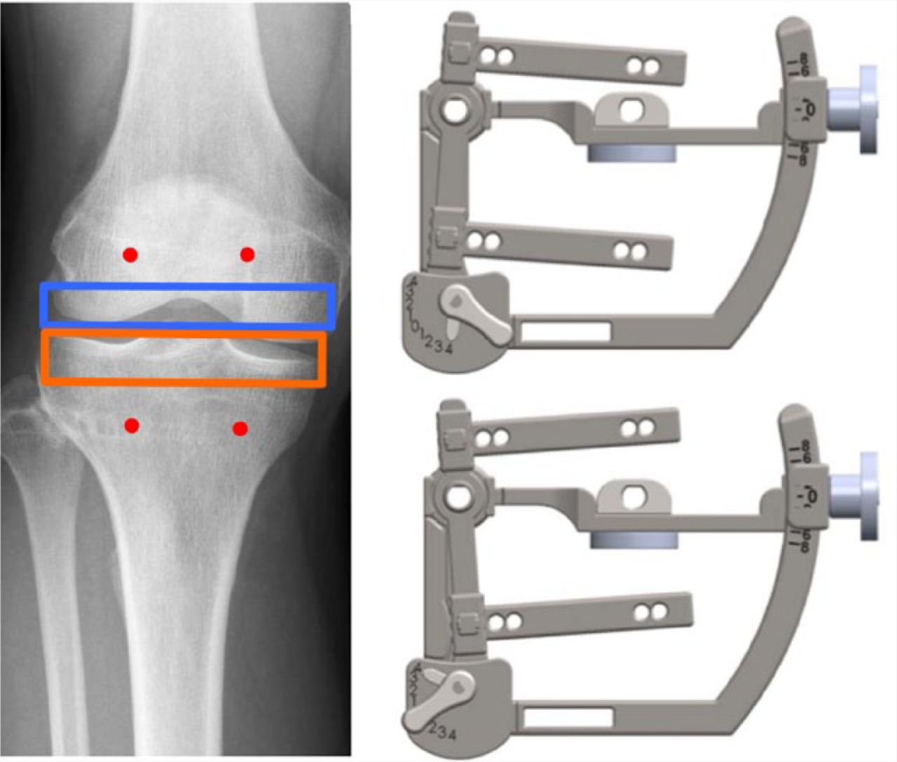
Fig. 15
The default function produces a rectangular extension gap perpendicular to the tibial axis, of the correct size and centred on the lateral joint line (left). Kinematics can be optionally introduced in a controlled fashion to allow a compromise to be reached if there is a large discrepancy between the medial and lateral joint line heights (right).

Fig. 16
ADVANTicS system joint level finder connects onto joint gap guides and pins for tibial and femoral resections, simultaneously (cadaver).

Fig. 17
The proposed ADVANTicS technique links the femoral AP size selection with a corresponding tibial posterior slope. The system selects the nearest available size of femoral implant and adjusts the tibial slope to ‘fine-tune’ the flexion gap to the optimal size.

Fig. 18
ADVANTicS Flexion Gap Device. The femoral AP resections are interlinked with the tibial resection posterior slope for an optimised flexion gap size and femoral AP size (cadaver).
The net result is that the femoral component is positioned aligned with the distal femoral axis of rotation (Fig. 19) and the implants are positioned perpendicular to the tibial axis for symmetrical loading. The larger medial femoral condyle radius is effectively reduced to match the lateral condyle with a corresponding elevation of the medial tibial plateau. (Fig.20). Femoral component internal rotation is avoided. This maintains the cylindrical biomechanics of knee flexion and achieves the benefits of anatomical implant positioning without oblique implant positioning being necessary but with the possibility for controlled and moderated coronal angulation to account for individual anatomy.

Fig. 19
Schematic representation of the new anatomic individualised (ADVANTicS) technique. The larger medial femoral condyle radius is reduced to match the lateral condyle radius. Tension on the patella and soft tissue is avoided. The single axis of rotation passing through the centres of both femoral condyles remains unchanged and oblique implant positioning is avoided.

Fig. 20
Reducing the radius of the medial femoral condyle and raising the medial tibial plateau proportionately does not alter the axis of rotation. The spatial relationship and the biomechanics between femur and tibia remain the same.
Conflict of Interest
The author is directly involved in the development of ADVANTicS instrumentation. Both the author and institution have a commercial interest in this development.
Surgeons interested in reading a more detailed explanation of the ADVANTicS technique or who wish to be involved with the project can visit: www.advanticstka.com for further information.
References
1 No authors listed. The National Joint Registry 11th Annual Report. http://www.njrcentre.org.uk (date last accessed 13 June 2016). Google Scholar
2 No authors listed. http://www.nice.org.uk (date last accessed 13 June 2016). Google Scholar
3 Dakin H , GrayA, FitzpatrickR, MaclennanG, MurrayD; KAT Trial Group. Rationing of total knee replacement: a cost-effectiveness analysis on a large trial data set. BMJ Open2012;2:e000332.CrossrefPubMed Google Scholar
4 Jenkins PJ , ClementND, HamiltonDF, et al.. Predicting the cost-eefectiveness of total hip and knee replacement. Bone Joint J2013;95-B:115-121. Google Scholar
5 Kurtz S , OngK, LauE, MowatF, HalpernM. Projections of primary and revision hip and knee arthroplasty in the United States from 2005 to 2030. J Bone Joint Surg[Am]2007;89-A:780-785CrossrefPubMed Google Scholar
6 Baker PN , van der MeulenJH, LewseyJ, GreggPJ; National Joint Registry for England and Wales. The role of pain and function in determining patient satisfaction after total knee replacement. Data from the National Joint Registry for England and Wales. J Bone Joint Surg [Br]2007;89-B:893-900.CrossrefPubMed Google Scholar
7 Bourne RB , ChesworthBM, DavisAM, MahomedNN, CharronKD. Patient satisfaction after total knee arthroplasty: who is satisfied and who is not?Clin Orthop Relat Res2010;468:57-63.CrossrefPubMed Google Scholar
8 Robertsson O , DunbarM, PehrssonT, KnutsonK, LidgrenL. Patient satisfaction after knee arthroplasty: a report on 27,372 knees operated on between 1981 and 1995 in Sweden. Acta Orthop Scand2000;71:262-267.CrossrefPubMed Google Scholar
9 No authors listed. New Zealand Joint Registry. http://www.nzoa.org.nz/nz-joint-registry (date last accessed 13 June 2016). Google Scholar
10 No authors listed. Patient Reported Outcome Measures. http://www.hscic.gov.uk/proms (date last accessed 13 June 2016).CrossrefPubMed Google Scholar
11 Nam D , NunleyRM, BarrackRL. Patient dissatisfaction following total knee replacement: a growing concern?Bone Joint J2014;96-B:96-100.CrossrefPubMed Google Scholar
12 Dossett HG , EstradaNA, SwartzGJ, LeFevreGW, KwasmanBG. A randomised controlled trial of kinematically and mechanically aligned total knee replacements: two-year clinical results. Bone Joint J2014;96-B:907-913.CrossrefPubMed Google Scholar
13 Howell SM , HowellSJ, KuznikKT, CohenJ, HullML. Does a kinematically aligned total knee arthroplasty restore function without failure regardless of alignment category?Clin Orthop Relat Res2013;471:1000-1007.CrossrefPubMed Google Scholar
14 Beard DJ , HarrisK, DawsonJ, et al.. Meaningful changes for the Oxford hip and knee scores after joint replacement surgery. J Clin Epidemiol2015;68:73–79.CrossrefPubMed Google Scholar
15 Tokuhara Y , KadoyaY, NakagawaS, KobayashiA, TakaokaK. The flexion gap in normal knees. An MRI study. J Bone Joint Surg [Br]2004;86-B:1133-1136.CrossrefPubMed Google Scholar
16 Parratte S , PagnanoMW. Instability after total knee arthroplasty. J Bone Joint Surg [Am]2008;90-A:184-194. Google Scholar
17 Freeman MA , PinskerovaV. The movement of the knee studied by magnetic resonance imaging. Clin Orthop Relat Res2003;410:35-43.CrossrefPubMed Google Scholar
18 Monk AP , ChojiK, O’ConnorJJ, GoodfellowJW, MurrayDW. The shape of the distal femur. Bone Joint J2014;96-B:1623-1630.CrossrefPubMed Google Scholar
19 Eckhoff DG , DwyerTF, BachJM, SpitzerVM, ReinigKD. Three-dimensional morphology of the distal part of the femur viewed in virtual reality. J Bone Joint Surg [Am]2001;83-A:43-50.CrossrefPubMed Google Scholar
20 Eckhoff DG , BachJM, SpitzerVM, et al.. Three-dimensional morphology and kinematics of the distal part of the femur viewed in virtual reality. Part II. J Bone Joint Surg [Am]2003;85-A:97-104.CrossrefPubMed Google Scholar
21 Eckhoff DG , BachJM, SpitzerVM, et al.. Three-dimensional mechanics, kinematics, and morphology of the knee viewed in virtual reality. J Bone Joint Surg [Am]2005;87-A:71-80.CrossrefPubMed Google Scholar
22 Komistek RD , DennisDA, MahfouzM. In vivo fluoroscopic analysis of the normal human knee. Clin Orthop Relat Res2003;410:69-81.CrossrefPubMed Google Scholar
23 Dennis DA , KomistekRD, MahfouzMR, HaasBD, StiehlJB. Multicenter determination of in vivo kinematics after total knee arthroplasty. Clin Orthop Relat Res2003;416:37-57.CrossrefPubMed Google Scholar
24 Singh G , TanJH, SngBY, et al.. Restoring the anatomical tibial slope and limb axis may maximise post-operative flexion in posterior-stabilised total knee replacements. Bone Joint J2013;95-B:1354-1358.CrossrefPubMed Google Scholar
25 Cherian JJ , KapadiaBH, BanerjeeS, et al.. Mechanical, Anatomical, and Kinematic Axis in TKA: Concepts and Practical Applications. Curr Rev Musculoskelet Med2014;7:89-95.CrossrefPubMed Google Scholar
26 Bellemans J , ColynW, VandenneuckerH, VictorJ. The Chitranjan Ranawat award: is neutral mechanical alignment normal for all patients? The concept of constitutional varus. Clin Orthop Relat Res2012;470:45-53.CrossrefPubMed Google Scholar
27 Parratte S , PagnanoMW, TrousdaleRT, BerryDJ. Effect of postoperative mechanical axis alignment on the fifteen-year survival of modern, cemented total knee replacements. J Bone Joint Surg [Am]2010;92-A:2143-2149.CrossrefPubMed Google Scholar
28 Chin PL , YangKY, YeoSJ, LoNN. Randomized control trial comparing radiographic total knee arthroplasty implant placement using computer navigation versus conventional technique. J Arthroplasty2005;20:618-626.CrossrefPubMed Google Scholar
29 Chauhan SK , ScottRG, BreidahlW, BeaverRJ. Computer-assisted knee arthroplasty versus a conventional jig-based technique. A randomised, prospective trial. J Bone Joint Surg [Br]2004;86-B:372-377.CrossrefPubMed Google Scholar
30 Anderson KC , BuehlerKC, MarkelDC. Computer assisted navigation in total knee arthroplasty: comparison with conventional methods. J Arthroplasty2005;20:132-138.CrossrefPubMed Google Scholar
31 Kamat YD , AurakzaiKM, AdhikariAR, et al.. Does computer navigation in total knee arthroplasty improve patient outcome at midterm follow-up?Int Orthop2009;33:1567-1570.CrossrefPubMed Google Scholar
32 Spencer JM , ChauhanSK, SloanK, TaylorA, BeaverRJ. Computer navigation versus conventional total knee replacement: no difference in functional results at two years. J Bone Joint Surg [Br]2007;89-B:477-480.CrossrefPubMed Google Scholar
33 Molfetta L , CaldoD. Computer navigation versus conventional implantation for varus knee total arthroplasty: a case-control study at 5 years follow-up. Knee2008;15:75-79.CrossrefPubMed Google Scholar
34 Abdel MP , ParratteS, BlancG, et al.. No benefit of patient-specific instrumentation in TKA on functional and gait outcomes: a randomized clinical trial. Clin Orthop Relat Res2014;472:2468-2476.CrossrefPubMed Google Scholar
35 Sassoon A , NamD, NunleyR, BarrackR. Systematic review of patient-specific instrumentation in total knee arthroplasty: new but not improved. Clin Orthop Relat Res2015;473:151-158. Google Scholar
36 Ritter MA , DavisKE, MedingJB, et al.. The effect of alignment and BMI on failure of total knee replacement. J Bone Joint Surg [Am]2011;93-A:1588-1596.CrossrefPubMed Google Scholar
37 Calliess T , EttingerM, Stukenborg-ColsmannC, WindhagenH. [Custom-fit kinematic alignment in total knee arthroplasty using PSI : the story of ShapeMatch technology]. Orthopade2016;45:314-321.(In German) Google Scholar
38 Howell SM , PapadopoulosS, KuznikKT, HullML. Accurate alignment and high function after kinematically aligned TKA performed with generic instruments. Knee Surg Sports Traumatol Arthrosc2013;21:2271-2280.CrossrefPubMed Google Scholar
39 Hutt JR , LeBlancMA, MasséV, LavigneM, VendittoliPA. Kinematic TKA using navigation: surgical technique and initial results. Orthop Traumatol Surg Res2016;102:99-104.CrossrefPubMed Google Scholar
40 Abdel MP , OussedikS, ParratteS, LustigS, HaddadFS. Coronal alignment in total knee replacement: historical review, contemporary analysis, and future direction. Bone Joint J2014;96-B:857-862.CrossrefPubMed Google Scholar
41 Sikorski JM . Alignment in total knee replacement. J Bone Joint Surg [Br]2008;90-B:1121-1127. Google Scholar
42 Thienpont E , CornuO, BellemansJ, VictorJ. Current opinions about coronal plane alignment in total knee arthroplasty: A survey article. Acta Orthop Belg2015;81:471-477.PubMed Google Scholar
43 Donaldson J , JoynerJ, TudorF. Current Controversies of Alignment in Total Knee Replacements. Open Orthop J2015;9:489-494.CrossrefPubMed Google Scholar
44 Howell SM , PapadopoulosS, KuznikK, GhalyLR, HullML. Does varus alignment adversely affect implant survival and function six years after kinematically aligned total knee arthroplasty?Int Orthop2015;39:2117-2124.CrossrefPubMed Google Scholar
45 No authors listed. Conformis. www.conformis.com (date last accessed 13 June 2016). Google Scholar
46 Babazadeh S , DowseyMM, SwanJD, StoneyJD, ChoongPF. Joint line position correlates with function after primary total knee replacement: a randomised controlled trial comparing conventional and computer-assisted surgery. J Bone Joint Surg [Br]2011;93-B:1223-1231.CrossrefPubMed Google Scholar
47 No authors listed. Knee Reconstruction. www.depuysynthes.com/hcp/knee/products/qs/ATTUNE-Knee-System (date last accessed 13 June 2016). Google Scholar
48 No authors listed. Zimmer Persona Knee. www.zimmer.com/medical-professionals/products/knee/persona-knee.html (date last accessed 13 June 2016). Google Scholar
49 No authors listed. Journey II BCS. www.smith-nephew.com/professional/products/all-products/journey-active-knee-solutions/journey-ii-bcs-/ (date last accessed 13 June 2016). Google Scholar
