


Introduction
The Gough-Stewart platform (GSP) is a variable strut, programmable octahedral hexapod that uses six computer-controlled linear actuators to support a moveable base. These devices have been developed for a wide range of commercial uses including flight and vehicle simulators, high-precision tools, mining machines and medical instruments including programmable external fixators.
The prototype hexapod external was introduced in France in 1986 and improvements in component design and computer algorithms have broadened the clinical repertoire of these devices. An increase in the number of available systems is expected in the next 18 months, owing to the expanding indications for this technology, in addition to termination of long standing patent arrangements and the associated commercial imperatives.
These versatile platforms have clinical applications in acute fracture fixation; deformity surgery and limb salvage and provide an attractive combination of flexibility and ease of application.
Representation of three-dimensional objects in two-dimensional space
Contemporary orthopaedic practice is illustrated by two-dimensional radiological images, presented in standard anteroposterior and medio-lateral orthogonal planes. These are simplified ‘two axis’ representations of complex three-dimensional objects. It would not be possible to use an automated device to predictably reconstruct a deformed bone without the ability to mathematically describe the positions of the individual components.
Pythagoras (c.570 BCE – c.495 BCE) and Euclid (c.300 BCE) are credited with defining the fundamentals of 2D and 3D geometry, and this was refined by Appolonius (c.262 BCE – c. 190 BCE), who anticipated Cartesian geometry by 1800 years. Pappus (c. A.D. 290 – c. 350) introduced a formalised approach to this area of mathematics and described a form of geometry that was not based on the concept of distance. This began with the study of the relationship between points and lines in 2D space and developed into the discipline of projective geometry.
The introduction of realism in art in the Italian Renaissance relied on the ability to represent 3D objects in 2D space and led to the study of linear perspective. During the 15th century, Brunelleschi (1377 – 1446) studied linear perspective in art and this led to the development of projective geometry as a mathematical discipline. Desargues (1591-1661) developed an alternative method for constructing perspective drawings and is also credited with introducing concepts including the point, line and plane at infinity.
Decartes (1596 – 1650) formalised a system of co-ordinate geometry thereby allowing a point in space to be described as a set of numbers. Algebraic equations could now be expressed as geometric shapes in a 2D coordinate system and conversely, shapes could be described by equations. This is the basis of the orthogonal system that is used to describe planes of deformity in contemporary orthopaedic practice.
These contributions let to the development of projective geometry as a unique field in mathematics. It is now commonly thought of as the evaluation of the space in which geometrical objects exist and act and is the conceptual basis for the understanding of automated deformity correction and fracture reduction.
The study of kinematics is central to many aspects of orthopaedic surgery and biomechanics and involves the study of the geometry of motion in a material body with two or more moving components.
Such a component is termed a kinematic link1 and represents the basic element of a kinematic system. These concepts are usually applied to the analysis of the motion of the components of a machine and this is typically represented by a model, consisting of moving parts that articulate at predefined axes. Analysis of fracture and deformity in long bones requires each segment to be considered as an individual kinematic link and the kinematic chains in the majority of anatomical situations are open.2,3
Chasels (1793 – 1880) was the first to recognise that most general rigid body displacements can be produced by translation and rotation along a single axis composed only of a rotational and translational component.4 A firm understanding of projective geometry and kinematics allows the description of 3D deformity and application of Chasles’ theorem and axis can be used to establish the position and direction of the associated vectors.
This is of fundamental importance for automated fracture reduction or deformity correction, and forms the basis for simultaneous correction of all components of complex skeletal deformity. This seemingly complex mathematical process underpins the 3D transformations that make the hexapod fixator such a powerful tool in clinical practice.
Automated manipulation of objects in 3D space
The principles employed by the hexapod fixator is that of a parallel manipulator; a machine, made of closed-loops in which mobile joints connect an end effector to a base by at least two independent kinematic chains.
Definition of the components of a fixator and the deformity of a fracture or bone is straightforward. It is substantially more difficult to define the spatial relationships of a complex 3D object. To achieve this and provide simplicity of use, the technique of forward kinematics uses the joint parameters to compute the direct relationship between actuator positions and the configuration of the manipulator and inverse kinematics reverses this calculation to determine the joint parameters that achieves a desired configuration.5
In 1812, Cauchy considered the flexibility of 3D polyhedra, where each joint could pivot or hinge and proved that a convex polyhedron with invariant facets must be rigid.6 The consequence of this theorem was the realisation that if a polyhedron (the fixator in this case) were constructed with flexible hinges at each vertex but rigid struts, then a structure with potentially infinite configurations would be formed.
This determined that the configuration of a 3D solid in general and an octahedron in particular could be represented mathematically and that the change in shape could therefore also be represented mathematically. This provided the theoretical basis for using an automated device to produce a predictable change in orientation of one solid body in respect of a second or a segment of bone in respect of a second segment.
The first multi-degree-of-freedom parallel kinematic system was designed in 1931 when Gwinnett received a patent for a motion simulator for use in the film industry.7 The design was based on a parallel spatial mechanism but a prototype was never produced. The first industrial parallel robot was a spray-painting machine designed by Pollard in 1934 and patented 1942, but this device was never built.8 In 1949, Gough designed an automated tyre tester based on a parallel manipulator formed from six linear actuators supporting a movable base and this was operational in 1954-5.9,10
In 1965, Stewart11 published the design for a flight simulator with parallel platforms but allowing for 6° of freedom, and in 1967, Cappel built a motion simulator based on a hexapod configuration.12 This type of robot has since been developed for use in areas ranging from astronomy to flight simulators and medical applications are becoming increasingly popular.
The use of external fixators in fracture reduction and long bone deformity correction
Hippocrates (c. 460 BCE - 380 BCE) is credited with the first description of an externally applied device used to reduce and stabilise fractures of the lower limb. This comprised a system of four rods “made of the cornel tree” bound to the patient’s extremity then folded to maintain stability.13 A similar device made from iron rings and rods was used by Paracelcus (1493 – 1541).14
In 1840, Malgaigne designed the pointe métallique, a belt attached to a metallic band, which was tightened around the limb until a metal nail reduced the fracture.15,16 In 1843, he developed the griffe métallique, a device applied externally with a four-pronged clamp and turnbuckle that allowed compression for the treatment of patellar fractures.15,16
In 1893 Keetley became the first to use bicortical percutaneous pins16 and in 1897 Parkhill invented the ‘bone clamp’ and defined the concept of unilateral external fixation.17 This consisted of four fracture-spanning plates, secured by a rigid external plate bolted to one of two half-pins, proximal and distal to the fracture site.17 Lambott also used this pin configuration after open fracture reduction, initially mounting the pins between two heavy metal plates providing rigidity suitable for early weight-bearing.18 In 1934 Anderson designed the ‘Fracture Robot’, a device using transfixation pins that permitted multi-planar adjustment of fracture fragments and was the first to advocate early weight bearing and joint mobilisation.19
In 1938 Hoffmann described a modular external fixator with the facility to reduce and make post-operative corrections to the alignment of fragments in three planes.20,21 This was the prototype monolateral adjustable fixator and continues in widespread use in its second incarnation. In the period following the Second World War, Ilizarov developed a fine wire circular fixator for use in the management of fractures, non-unions and deformity. The Ilizarov external fixator was patented in 1952 and has developed into a highly versatile apparatus that is in widespread contemporary use.22-24
Ilizarov used the term “regenerate” to describe the bone formed in distraction osteogenesis and investigated the biological and mechanical factors that were of primary importance. These principles continue to influence surgeons involved in fracture management and skeletal reconstruction. De Bastiani popularised distraction osteogenesis in Europe with a mono-body external fixator and introduced the term ‘callotasis’.25 The technique involved a tissue preserving osteotomy, latent period and distraction at 1 mm per day.
Combining projective geometry, the parallel manipulator and the external fixator
In 1986, Moniot26 patented a device “for three-dimensional positioning of two pieces of any kind, in particular of two bone parts.” Seidel and Kostin27 were awarded a patent for a fracture reduction device in 1989, having filed their patent in 1984. These patents describe the prototypes of hexapod-based fracture reduction robots, although neither of these designs were ever introduced into clinical practice.
The Eisenberg Ringfixateur28 was introduced in 1996 and consisted of a double ring system with tensioned wires and Schanz screws. 3D manipulation of fracture fragments was achieved with six computer controlled adjustable telescopic struts. This device was introduced into clinical practice but there are no reports of the results of treatment, and the device is no longer available.
Seide et al29 developed an Hexapod fixator that involved 12 ball joints and six manually-operated linear distractors in a Hexapod configuration. Their initial description in 1996 was followed by a summary of their experience with 16 tibial fractures, nonunions and malalignment. They reported mean residual angular deformities of 1° in each plane and of final translation 3.5 mm (anteroposterior) and 1.5 mm (lateral).30
The Taylor Spatial Frame (TSF) (Fig. 1), was developed by HS and JC Taylor of Memphis, Tennessee, and patented in 1997.31 This is also an external fixator based on a two-ring system, linked by six variable-length struts connected to the rings with universal joints at either end. The principle of the TSF is that the relative positions of the rings can be defined precisely by the lengths of the six struts, which can then be altered to change the position of the rings in predictable and accurate manner with a computer program allowing a simultaneous six axis correction (x, y, z, pitch, roll, & yaw).
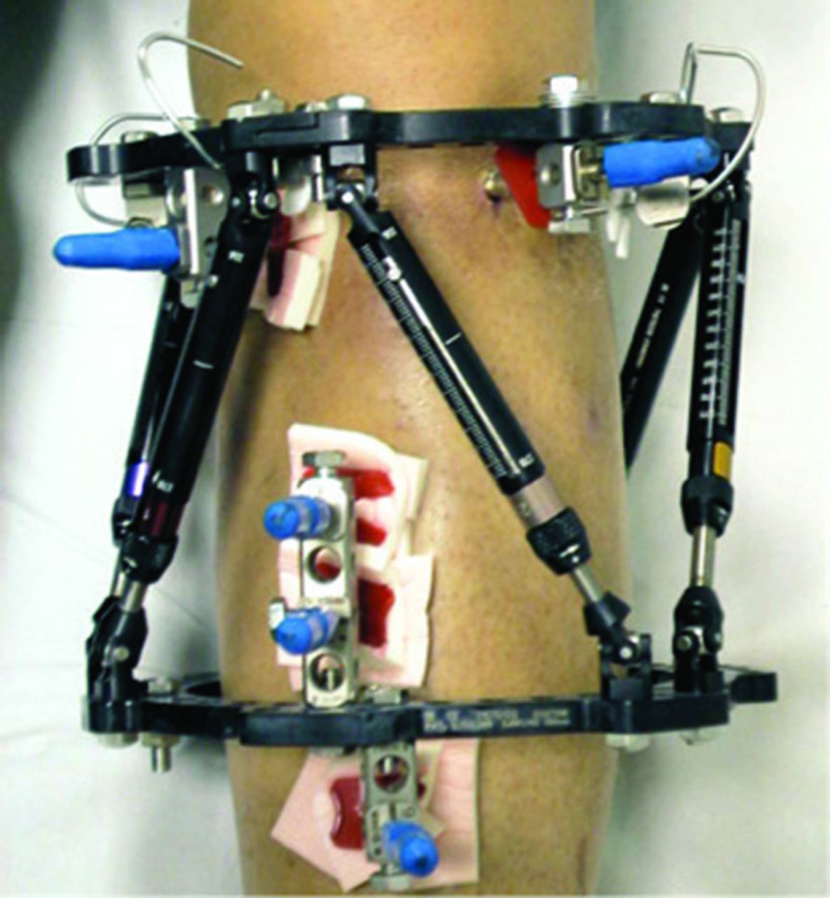
Fig. 1
The Taylor Spatial Frame.
The device has the theoretical capability of achieving deformity correction accurate to 1° and 1 mm in all planes. The initial orientation of the segments of deformed bone is determined from orthogonal radiographs and the position of the ring in relation to a predefined bony point is measured.
The configuration of the initial construct is defined by the strut lengths and the position of the struts in the corrected position is calculated and a daily programme of incremental correction generated and issued to the patient. The precision of the deformity correction however is dependent on accurate acquisition and interpretation of post-operative radiographs, with clinical assessment of rotational deformity. Any error is easily corrected by recalculating the programme of corrections based on follow-up radiographs (Fig. 2a to 2c).
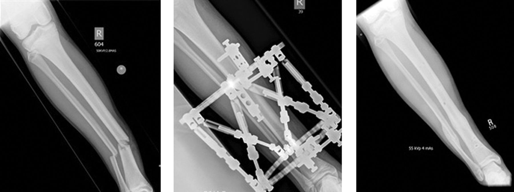
Fig. 2
Figure 2a, b, c: Tibial fracture in a 14-year-old male.
Samchukov et aldeveloped a computerised hexapod system based on the classic Ilizarov technique and apparatus. The perceived advantages of their system include frame stability, with independent acute and gradual strut length adjustment decreasing number of strut exchanges during treatment. Software developments include deformity analysis based on the bone segment axis, pre-operative planning with efficient frame pre-construction and planning of multi-stage correction. This device has been used on 369 patients to date, but no formal publication of results is currently available.
The sceptics’ view is that the programmable hexapod adds little to established fixator systems, particularly the Ilizarov external fixator. Inaccurate application of this device however, results in incomplete correction or secondary deformity, which requires alteration of the fixator. Correction with the Ilizarov external fixator usually occurs in series, with sequential correction of deformity also requiring modification of the fixator, which can be time-consuming and requires significant expertise.
The hexapod system offers a technically straightforward device that allows simultaneous correction of all elements of deformity at a rate that is tolerated by the patient and minimises the risk of injury to adjacent structures. If there is residual deformity, reprogramming is straightforward and does not require reconfiguration, making complex correction possible in the context of a busy outpatient clinic
Although the geometric and mathematical principles underpinning the use of these devices are complex, they translate into an orthopaedic device that is straightforward and easy to use in clinical practice.
1 1. Hartenberg RS, Denavit J. Kinematic synthesis of linkages. McGraw-Hill, 1964. Google Scholar
2 2. Fischer O. Kinematik Organischer Gelenke. Braunschweig: Friedrich Vieweg Und Sohn, 1907. Google Scholar
3 3. Demster WT. The anthropometry of body action. Annals New York Academy of Sciences 1955;63:559-585. Google Scholar
4 4. Chasles M. Note sur les propriétés générales du système de deux corps semblables entr'eux et placés d'une manière quelconque dans l'espace; et sur le déplacement fini ou infiniment petit d'un corps solide libre. Bulletin des Sciences Mathematiques, Astronomiques, Physiques et Chimiques 1830;14:321-326. Google Scholar
5 5. Paul RP. Robot manipulators: mathematics, programming, and control : the computer control of robot manipulators. Cambridge, Massachusetts: MIT, 1981. Google Scholar
6 6. Cauchy A. Deuxieme memoire sur les polygones et les polyedres. Journal de l'Ecole Polytechnique 1813:87-98. Google Scholar
7 7. Gwinnett JE. Amusement device. Vol. US1789680 A, A63G31/00, A63J13/00, A63G31/16 ed. United States, 1931. Google Scholar
8 8. Pollard WLG. Spray painting machine. Vol 2,213,108. United States, 1942. Google Scholar
9 9. Gough VE. Contribution to discussion to papers on research in automobile stability and control and in tyre performance, by Cornell staff. Proc Auto Div Instn Mech Engrs 1956;7:392. Google Scholar
10 10. Gough VE, Whitehall SG. Universal tyre test machine. Ninth International Technical Congress F.I.S.I.T.A. Instution of Mechanical Engineers, 1962. Google Scholar
11 11. Stewart D. A platform with six degrees of freedom. Proc Instn Mech Engrs 1965;180:371-86. Google Scholar
12 12. Cappel KL. Motion simulator. Vol 3,295,United States, 1967. Google Scholar
13 13. Adams F. The Genuine Works of Hippocrates, Volume 1. Oxford: Sydenham Society, 1849. Google Scholar
14 14. Malgaigne JF, Hamby WB. Surgery and Ambroise Paré. University of Oklahoma Press, 1965. Google Scholar
15 15. Mears DC. External skeletal fixation. Baltimore/London: Williams and Wilkins, 1983. Google Scholar
16 16. Browner BD. Skeletal trauma. 1. Saunders, 2003. Google Scholar
17 17. Parkhill C. A new apparatus for the fixation of bones after resection and in fractures with a tendancy to displacement. Trans Am Surg Assoc 1857;15:251-266. Google Scholar
18 18. Lambotte A. The operative treatment of fractures: report of fractures committee. Br Med J 1912;2:1530. Google Scholar
19 19. Anderson R. An automatic method of treatment for fractures of the tibia and fibula. Surgery, Gynacology, Obstetrics 1934;58. Google Scholar
20 20. Hoffmann R. Closed osteosynthesis with special references to war surgery Acta Chir Scand 1942;86:255-261. Google Scholar
21 21. Hoffmann R. Rotules à os" pour la "réduction dirigée", non sanglante, des fractures ("ostéotaxis"). Helv Med Acta 1938;5:844-850. Google Scholar
22 Ilizarov GA . The tension-stress effect on the genesis and growth of tissues part II: the influence of the rate and frequency of distraction. Clin Orthop Relat Res1989;239:263–285. Google Scholar
23 Ilizarov GA . The tension-stress effect on the genesis and growth of tissues. Part I. The influence of stability of fixation and soft-tissue preservation. Clin Orthop Relat Res1989;238:249–281.PubMed Google Scholar
24 Ilizarov GA . Clinical application of the tension-stress effect for limb lengthening. Clin Orthop Relat Res1990;250:8–26.PubMed Google Scholar
25 De Bastiani G , AldegheriR, Renzi-BrivioL, TrivellaG. Limb lengthening by callus distraction (callotasis). J Pediatr Orthop1987;7:129–134.CrossrefPubMed Google Scholar
26 26. Moniot P. Dispositif de positionnement tridimensionnel de deux pièces quelconques, en particulier de deux parties d'os et permettant de modifier ledit positionnement. Vol. FR 2 576 774-AFrance, 1986. Google Scholar
27 27. Pislar SI, Kostin YN. Reducing fractures by providing simaltaneous correction of bone fragments in all planes. Vol. 1222261 A 61 B 17/58 USSR, 1989. Google Scholar
28 28. Weber CS, Seifert T, Ahnert H, Damm C, Guyenot V. Eisenberger Ringfixateur. Ein neuentwickeltes Ringfixationssystem. Medizintechnik 1996;116:61-64. Google Scholar
29 29. Seide K, Wolter D. Universal 3-dimensional correction and reposition with the ring fixator using the hexapod configuration. Unfallchirurg 1996;99:422-424. (In German). Google Scholar
30 Seide K , WolterD, KortmannHR. Fracture reduction and deformity correction with the hexapod Ilizarov fixator. Clin Orthop Relat Res1999;363:186–195.PubMed Google Scholar
31 31. Taylor HS, Taylor JC. Orthopaedic fixation device. In IU Smith and Nephew Richards (ed). 1997:1-24. Google Scholar
