


Abstract
Aims
Restoration of proximal medial femoral support is the keystone in the treatment of intertrochanteric fractures. None of the available implants are effective in constructing the medial femoral support. Medial sustainable nail (MSN-II) is a novel cephalomedullary nail designed for this. In this study, biomechanical difference between MSN-II and proximal femoral nail anti-rotation (PFNA-II) was compared to determine whether or not MSN-II can effectively reconstruct the medial femoral support.
Methods
A total of 36 synthetic femur models with simulated intertrochanteric fractures without medial support (AO/OTA 31-A2.3) were assigned to two groups with 18 specimens each for stabilization with MSN-II or PFNA-II. Each group was further divided into three subgroups of six specimens according to different experimental conditions respectively as follows: axial loading test; static torsional test; and cyclic loading test.
Results
The mean axial stiffness, vertical displacement, and maximum failure load of MSN-II were 258.47 N/mm (SD 42.27), 2.99 mm (SD 0.56), and 4,886 N (SD 525.31), respectively, while those of PFNA-II were 170.28 N/mm (SD 64.63), 4.86 mm (SD 1.66), and 3,870.87 N (SD 552.21), respectively. The mean torsional stiffness and failure torque of MSN-II were 1.72 N m/° (SD 0.61) and 16.54 N m (SD 7.06), respectively, while those of PFNA-II were 0.61 N m/° (SD 0.39) and 6.6 N m (SD 6.65), respectively. The displacement of MSN-II in each cycle point was less than that of PFNA-II in cyclic loading test. Significantly higher stiffness and less displacement were detected in the MSN-II group (p < 0.05).
Conclusion
The biomechanical performance of MSN-II was better than that of PFNA-II, suggesting that MSN-II may provide more effective mechanical support in the treatment of unstable intertrochanteric fractures.
Cite this article: Bone Joint Res 2020;9(12):840–847.
Article focus
-
Restoration of proximal medial femoral support is the keystone in the treatment of intertrochanteric fractures.
-
None of the available implants are effective in constructing the medial femoral support. Medial sustainable nail (MSN-II) is a novel cephalomedullary nail designed for this.
-
The aim of this study was to evaluate the biomechanical performance of MSN-II in the axial loading test, static torsional test, and cyclic loading test compared with proximal femoral nail anti-rotation (PFNA-II), which was widely used in unstable intertrochanteric fractures.
Key messages
-
The biomechanical performance of MSN-II was better than that of PFNA-II in the treatment of an unstable intertrochanteric fracture.
-
In the treatment of unstable intertrochanteric fractures, MSN-II may be an implant option for the reconstruction of the medial femoral support structure.
Strengths and limitations
-
Based on the reconstruction of the medial femoral support structure, we designed, developed, and updated a novel generation of MSN-II, and the previous generation of first-generation MSN (MSN-I) has proved to have good biomechanical properties.
-
The innovative design and adoption of 3D-printed osteotomy guide and needle guide ensure the uniformity of test conditions and reliability of the results.
-
The design of this study did not include MSN-I, because we have compared the differences between the MSN-I and PFNA-II in an earlier study. Therefore, this study compared MSN-II with PFNA-II, which was the most common cephalomedullary nail used for treatment of unstable intertrochanteric fracture.
Introduction
As one of the most common osteoporotic fractures in the elderly, intertrochanteric fractures account for approximately 40% to 50% of all hip fractures, of which 50% to 60% are unstable fractures.1,2 It is considered to be a potentially fatal disease with high mortality and disability rates due to the difficulty of treatment, which has placed a great burden on society.
At present, cephalomedullary nailing has been a widespread treatment for intertrochanteric fractures due to its good mechanical properties and minimally invasive procedure,3,4 and among which proximal femoral nail anti-rotation (PFNA-II) is the most common one.5,6 However, with the increase of application, the number of implant failures has also increased gradually, which was reported to be up to 20.5%.7 Implant failure has been reported to be related to loss of medial femoral support.8-11 Nonetheless, the existing cephalomedullary nails do not have the ability to reconstruct the medial support of intertrochanteric fracture.12
For reconstruction of the medial support of intertrochanteric fracture, we designed a novel intramedullary nail called medial sustainable nail (MSN-I) in previous research.13 It has been shown to provide better biomechanical performance in reducing displacement and anti-varus in an unstable intertrochanteric fracture (fracture type of AO/OTA 31-A2.3) by finite element analysis and biomechanical experiments. However, in further clinical application, MSN-I was found to be at risk of excessive sliding and cut-out due to its inadequate structural design, as the cephalic nail is composed of a sleeve and four helical blades. Furthermore, the MSN-I could not be well matched with the physiological curvature of the Chinese femur, which may increase the risk of anterior cortical impingement (Figure 1).14 Hence, we further improved MSN-I and named it MSN-II, which removed one spiral blade, added a limited sliding groove, and increased the curvature of the anterior arch of the nail according to the physiological curvature of the Chinese femur. The purpose was to increase the mechanical properties and provide effective medial support to reduce the risk of complications.
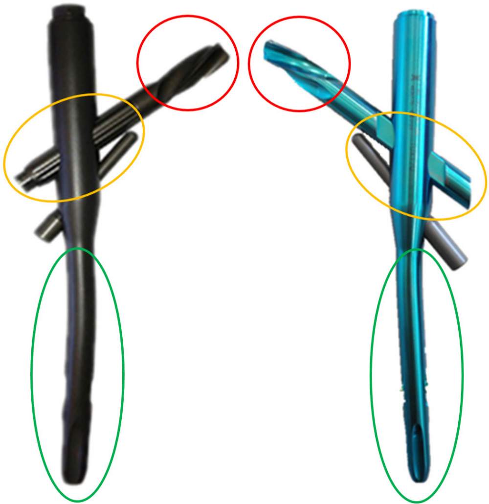
Fig. 1
The general view of improved parts between medial sustainable nail (MSN)-I (left) and MSN-II (right). MSN-II removed one spiral blade on the tip of the head nail (red circle), added a limited sliding groove on the middle parts and bevel modification on the tail of the head nails (yellow circle), and increased the curvature of the anterior arch of the nail shaft (green circle).
Therefore, this study intended to compare the biomechanical properties of MSN-II and PFNA-II in unstable intertrochanteric fractures (fracture type of AO/OTA 31-A2.3).
Methods
Specimens and preparation
A total of 36 left fourth-generation synthetic femur models (Sawbones, Model #3406 to 22; Pacific Research Laboratories, Vashon, Washington, USA) were randomly divided by mean into the MSN-II group and PFNA-II group. Each group underwent axial loading test, static torsional test, and cyclic loading test.
To ensure consistency of all specimens, we designed a 3D-printed needle guide and osteotomy guide (Figure 2). Under the needle guide, the nail and helical blade can be placed into the sawbones in the same location. The nail was inserted into the model following the manufacturer's manual. Then the nail was removed. With the osteotomy guide, the specimen was cut into the same fracture type, which is unstable intertrochanteric fracture pattern without posterior-medial support by two fracture lines along intertrochanteric. In the coronal plane, the first fracture line was above the lesser trochanter and the second was below the lesser trochanter. In the posterior to the proximal femur, the first line was located in the proximal of trochanteric crest while the second line was located on the distal of trochanteric crest.15 This peritrochanteric fracture pattern was similar as OTA/AO 31-A2.3 (Figure 3).
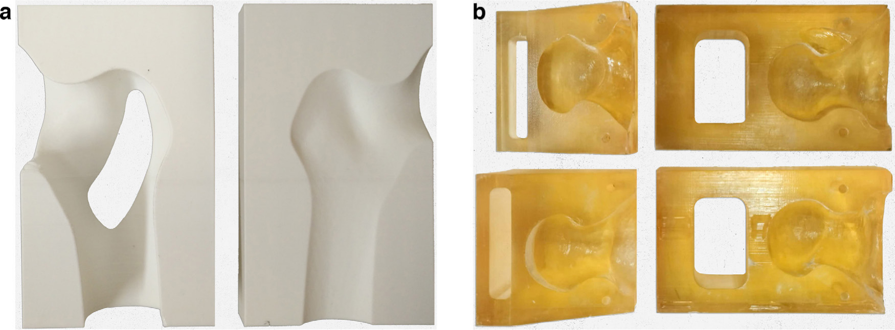
Fig. 2
a) 3D-printed nailing target of the cephalomedullary nail. b) 3D-printed osteotomy guide of AO/OTA type 31-A2.3 intertrochanteric fracture.
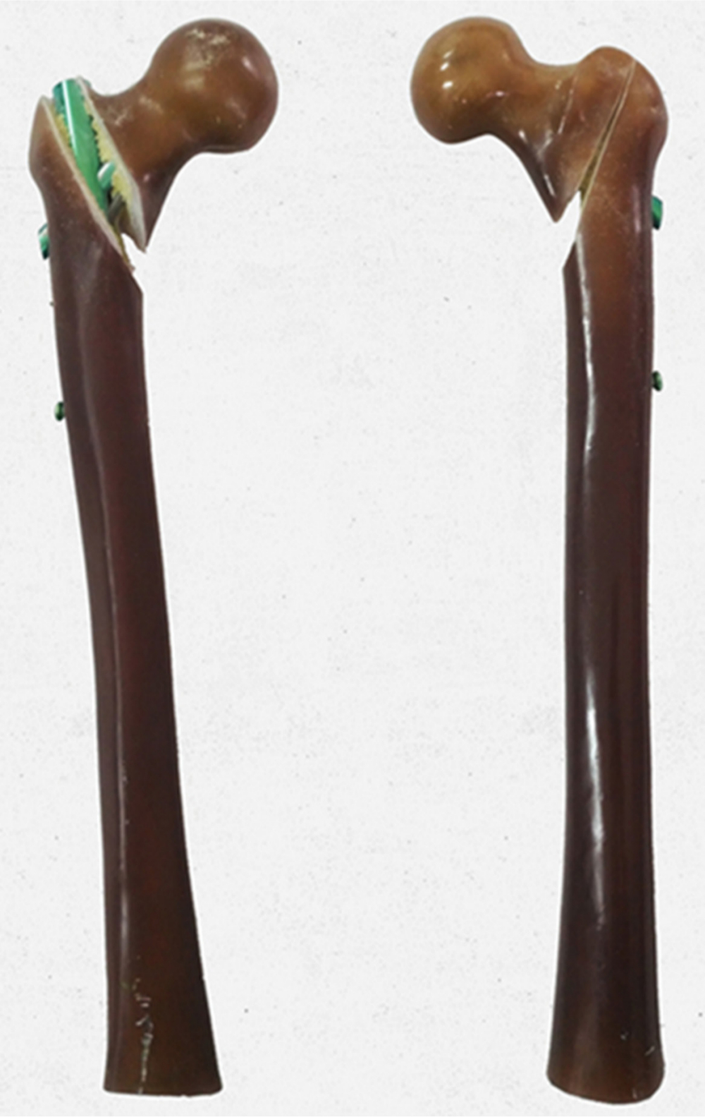
Fig. 3
Establishment of AO/OTA type 31-A2.3 intertrochanteric fracture model (the left side is anterior view, the right side is posterior view).
The nail was re-inserted in the specimen according to the operation manual after the fracture model was made. After cutting off the distal part of the femur at 40 cm distance from the tip of the greater trochanter, the femora were placed in steel cylinders and embedded in bismuth base low melting point alloy with a height of 10 cm.16
Biomechanical testing
Biomechanical testing was performed using an Electropuls E10000 (Instron, Canton, Massachusetts, USA) material testing machine and supporting analysis software (E10000 console software; Instron). The load was applied to the head of femur through a custom-made head adaptor acting as acetabulum for force transmission. In axial loading test and cyclic loading test, the specimen was fixed in a metal tube with bismuth base low melting point alloy, while the specimen was 10° hypsokinesis at the sagittal plane and 10° tilt inward at the coronal plane.17 In static torsional test, the specimen was fixed in a custom-made metal tube with bismuth base low melting point alloy, while the fracture surface of femoral end was paralleled with the horizontal plane.
Axial loading test
The specimens were fixed on a mechanical testing machine, and a force of 100 N was applied for three times of pre-loading at a speed of 5 mm/minute to eliminate the gap and creep between the model bone and the implant. Then the specimen was loaded with axial loading pressure starting from 0 N to the implant failure, with a rate of 5 mm/minute. The implant failure18 was defined as fracture of artificial bone or the implant. The data of axial load and displacement were recorded in the computer file, and the axial stiffness, ultimate load, and ultimate displacement were calculated according to the axial load-displacement curve.
Static torsional tests
Each specimen was fixed on the mechanical testing machine, and the head-neck fragment was able to rotate clockwise with the helical blade as the axis on the plane of the femoral fracture site. A 100 N preload was applied to the femoral head along the major axis of the femoral neck. Then torque was applied at a load rate of 5°/minute from 0 N m until implant failure. The implant failure was defined as torsional angle to 10° or fracture of specimen. The torque-angle curve and related data were saved in the computer file connected with the mechanical testing machine.
Cyclic loading test
The specimen was fixed on the mechanical testing machine, and was axial preloaded with 100 N load three times to eliminate the gap between the implant and Sawbones and the influence of creep and other factors on the results. The axial cyclic load was gradually loaded starting from 0 N and finishing at 2,100 N (representative walking of a 70 kg person), at a frequency of 1 Hz for 10,000 cycles (the 10,000 cycles were chosen to represent the approximate number of steps taken during the expected time of fracture consolidation over a period of six weeks).19,20 The load, displacement, and number of cycles were recorded by the computer connected with the mechanical testing machine.
Statistical analysis
The data were analyzed by SPSS 22.0 version (IBM, Armonk, New York, USA). Mechanical parameters were compared by using the independent-samples t-test. Mechanical parameters of each group were presented as mean ± SD. The level of significance was set at p < 0.05.
Results
Axial loading test
There was specimen fracture in both groups with the increase of load (Figure 4). The mean axial stiffness, vertical displacement, and maximum failure load of MSN-II were 258.47 N/mm (SD 42.27), 2.99 mm (SD 0.56), and 4,886 N (SD 525.31), respectively, while those of PFNA-II were 170.28 N/mm (SD 64.63), 4.86 mm (SD 1.66), and 3,870.87 N (SD 552.21), respectively. The differences between the two implants in axial stiffness, displacement distance, and maximum failure load were statistically significant (Table I).
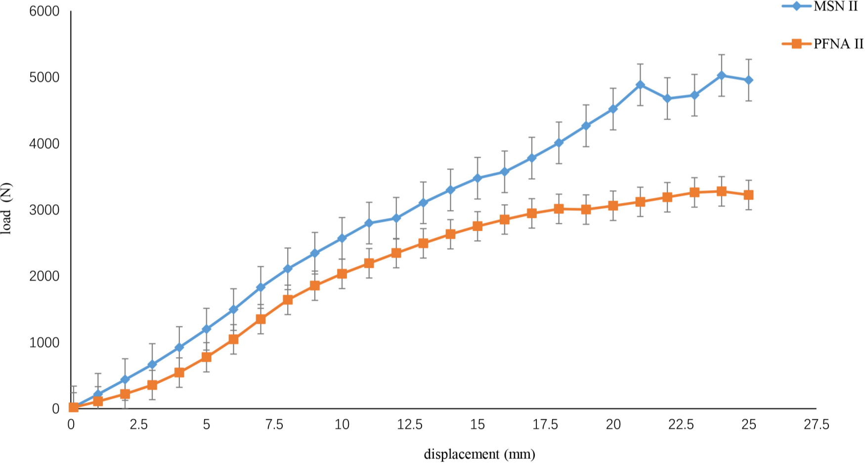
Fig. 4
Typical axial load-displacement curves. MSN, medialsustainable nail; PFNA, proximal femoral nail anti-rotation.
Table I.
The results of axial stiffness, maximum displacement, and failure load between the medial sustainable nail and proximal femoral nail anti-rotation groups.
| Variable | MSN-II (n = 6) | PFNA-II (n = 6) | p-value* |
|---|---|---|---|
| Mean axial stiffness, N/mm (SD) | 258.47 (42.27) | 170.28 (64.63) | 0.018 |
| Mean maximum displacement, mm (SD) | 2.99 (0.56) | 4.86 (1.66) | 0.040 |
| Mean failure load, N (SD) | 4,886 (525.31) | 3,870.87 (552.21) | 0.008 |
-
*
Independent-samples t-test.
-
MSN, medial sustainable nail; PFNA, proximal femoral nail anti-rotation.
The axial stiffness and failure load of MSN-II are higher than PFNA-II, while the maximum displacement is less than that of PFNA-II. The axial stiffness and failure load of MSN–II over PFNA-II goes up by 88.19 N/mm (51.7%) and 1,016 N (26.3%), which is 1.5-times and 1.3-times that of PFNA-II, respectively. Maximum displacement of MSN-II over PFNA-II goes down by 1.87 mm (38.5%).
Static torsional test
In static torsional test (Figure 5), the mean torsional stiffness, torsional angle, and failure torque of MSN-II were 1.72 N m/° (SD 0.61), 9.58° (SD 1.94°), and 16.54 N m (SD 7.06 N m), respectively, while those of PFNA-II were 0.61 N m/° (SD 0.39), 11.11° (SD 1.6°), and 6.6 N m (SD 6.65), respectively. The difference of torsion angle between the two groups was not statistically significant. The failure torque difference of the two groups was statistically significant (Table II). The torsional stiffness of MSN-II increased by 1.11 N m/°, which was 2.8-times that of PFNA-II.
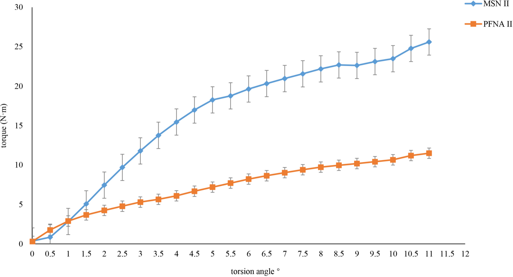
Fig. 5
Typical torque-torsion angle curves. MSN, medial sustainable nail; PFNA, proximal femoral nail anti-rotation.
Table II.
The results of torsional stiffness, torsion angle, and failure torque between the medial sustainable nail and proximal femoral nail anti-rotation groups.
| Variable | MSN-II (n = 6) | PFNA-II (n = 6) | p-value* |
|---|---|---|---|
| Mean torsional stiffness, N m/° (SD) | 1.72 (0.61) | 0.61 (0.39) | 0.003 |
| Mean torsion angle, ° (SD) | 9.58 (1.94) | 11.11 (1.6) | 0.166 |
| Mean failure torque, N m (SD) | 16.54 (7.06) | 6.6 (6.65) | 0.012 |
-
*
Independent-samples t-test.
-
MSN, medial sustainable nail; PFNA, proximal femoral nail anti-rotation.
Cyclic loading test
The displacement of MSN-II in 2,000, 4,000, 6,000, 8,000, and 10,000 cycles was 2.17 mm (SD 1.38), 1.68 mm (SD 2.15), 1.98 mm (SD 2.31), 2.8 mm (SD 3.11), and 3.91 mm (SD 2.95), respectively, while that of PFNA-II was 3.5 mm (SD 1.3), 3.28 mm (SD 1.74), 4.96 mm (SD 3.26), 5.53 mm (SD 3.19), and 7.17 mm (SD 2.31), respectively, in cyclic loading test (Figure 6). The displacement of MSN-II in each cycle of the nodes was less than that of PFNA-II, but the differences did not show obvious statistical significance (p > 0.05).
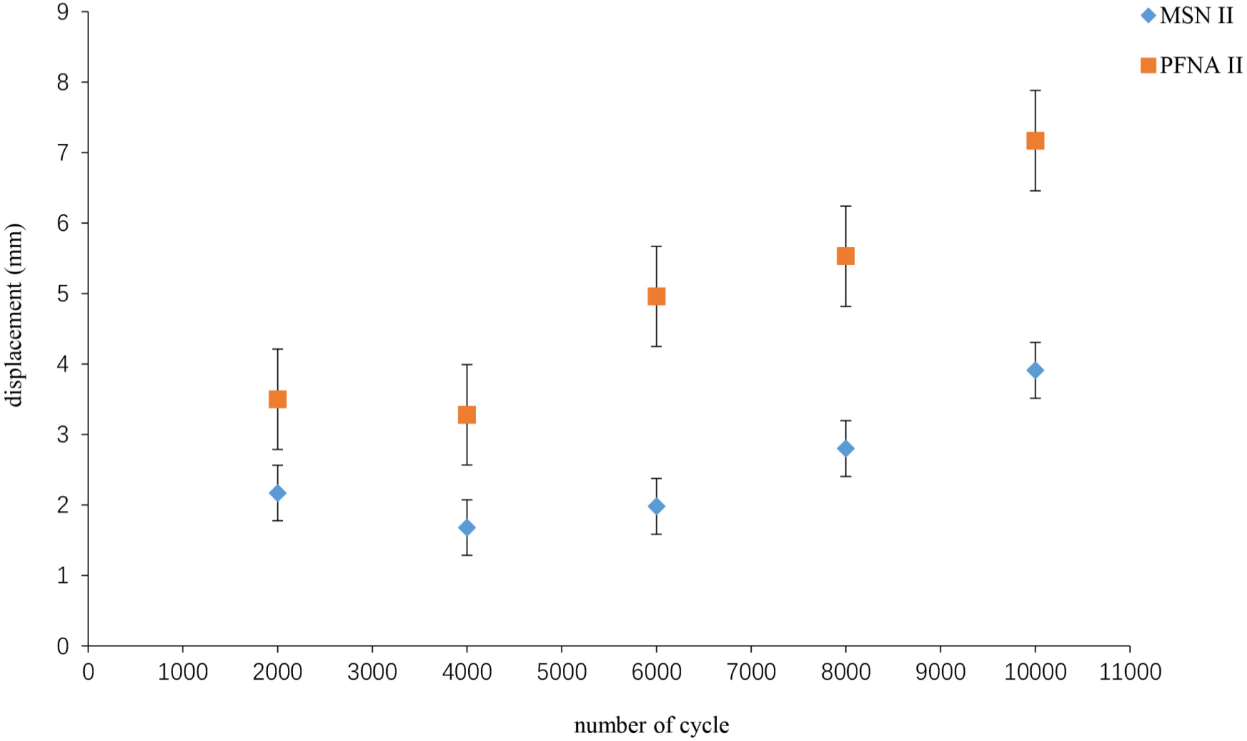
Fig. 6
Cycle number and displacement curves. MSN, medial sustainable nail; PFNA, proximal femoral nail anti-rotation.
In the cycle-displacement diagram, the displacement of each group in 4,000-cycles was less than that in 2,000-cycles. From 4,000-cycles to 10,000-cycles, the displacement increases as the number of cycles increases. The displacement of MSN-II group was less than that of PFNA-II at each cycle point.
Discussion
Due to lack of clear clinical evidence regarding the optimal surgical treatment, implant choice is often based on biomechanical performance.21,22 In this study, it was confirmed by biomechanical testing that MSN-II had better biomechanical performance than PFNA-II, so MSN-II might be a good choice for intertrochanteric fractures, especially those associated with posterior medial femoral comminuted bone fragment.
The axial stiffness of MSN-II was higher than that of PFNA-II in the axial loading test and the difference was statistically significant. The helical blade hole in the current intramedullary nail is the most likely to break as this is the site of the highest stress concentration.23,24 The stress of the helical blade hole in MSN-II was dispersed to the support point of the helical blade and the supporting nail hole by providing a novel support screw to buttress under the middle of the helical blade, forming a triangular structure at the proximal femur. Moreover, the working length of the helical blade was reduced by the supporting screw. All these measures may reduce the risk of fracture of the helical blade hole and helical blade. In this study, the helical blade of MSN-II was bent in the middle, but the hole did not break. The axial stiffness of MSN-II increased by 51.7% more than PFNA-II, which is 1.3-times that of PFNA-II. In addition, the restricted sliding slot of MSN-II ensures that excessive sliding is avoided on the basis of sliding compression, reducing the risk of cut-out. In this study, the displacement of the head-neck fragment in MSN-II was less than that of PFNA-II under the failure load, decreasing by 38%.
Torsional instability of an implant system is a predictor of the most common failure modes, including cut-out.25 In static torsional test, the torsional stiffness of MSN-II was obviously higher than that of PFNA-II. The number of helical blades of MSN-II was less than that of PFNA, for which the anti-rotation property was weaker, but the special support screw just across the fracture line not only filled in the medial femoral void, but also achieved biplanar fixation and increased anti-rotation efficiency. Therefore, the overall anti-rotation performance of MSN-II is better than PFNA-II. In this study, the torsion stiffness of MSN-II increased by 181.9%, which is 2.8-times more than the increase seen for PFNA-II. From the torque-angle curve, the initial torsion stiffness of MSN-II is less than that of PFNA-II, but the overall torsion stiffness is greater. This is consistent with the design of MSN-II. At the beginning of torsion, the helical blade is the main force against rotation. With the increase of torque and torsion angle, the supporting screw and the helical blade work together against rotation, resulting in a greater total anti-torsion performance than PFNA-II, which fixed the fractures by a single screw.
Theoretically, the longer the support screw is, the better the anti-rotation performance will be. However, if it is too long the supporting effect will be lost, which is only equivalent to PFNA. Although the anti-rotation performance is improved, it is easy to produce 'Z' effect26,27 and medial migration,28 which leads to cut-out. Moreover, the excessively long support screw cannot disperse the stress of the helical blades and the helical blade holes, which is easy to cause nail break and cut-out. In addition, excessively long screws could not occupy the medial void of femur, but would cause damage to the femoral head and lead to the adverse consequences of femoral head necrosis. Therefore, the length of the support screw is just across the fracture line, and it may be a better choice to achieve biplanar fixation. In this study, there was no cut-out or Z effect and less displacement in MSN-II, which suggests that the design of MSN-II is reasonable, with better torsional stiffness and fewer complications.
In cyclic fatigue test, MSN-II is more stable than PFNA-II, due to the displacement being smaller than PFNA-II in each cycle point. This indicates that MSN-II can effectively provide medial stability of intertrochanteric fractures and reduce the incidence of nonunion and implant failure. The cyclic displacement curve is a fold line, and the displacement of each group in 4,000 cycles point was smaller than that of the other. That is because before the 4,000 cycles, the head-neck fragment was gradually varus and the posterior medial femoral space gradually decreases with the increase of the number of cycles, and finally the fracture contact was formed and secondary stability was achieved. After 4,000 cycles, the head-neck fragment begins to slide distal due to the oblique fracture line. The slope of the cyclic-displacement curve in MSN-II is smoother than that of PFNA-II, which suggests that MSN-II has less displacement and better stability than PFNA-II. During weight-bearing, the intertrochanteric fracture patients stabilized with MSN-II may have less displacement of fracture site and be less likely to bring about hip pain and implant failure.
This study has several limitations. First-generation MSN (MSN-I) has not been included in this study, because the biomechanical differences between MSN-I and PFNA-II have been compared in previous studies. Only MSN-II and PFNA-II were included in the biomechanical comparison experiment. Also, while the study highlights the influence of different loading conditions on the nail, it does not recreate the in vivo environment, which may be a complex mix of some of these idealized conditions. This may require further research.
In conclusion, the axial stiffness, torsion stiffness, and stability of MSN-II are better than those of PFNA-II. It is feasible and reliable to reconstruct the medial support of femur by MSN-II, which may be more stable than PFNA-II in intertrochanteric fractures and is easier for patients to walk with loads on the ground, which may reduce postoperative complications.
Reference
1. Li M , Lv H-C , Liu J-H , et al. Differences in bone mineral density and hip geometry in trochanteric and cervical hip fractures in elderly Chinese patients . Orthop Surg . 2019 ; 11 ( 2 ): 263 – 269 . Crossref PubMed Google Scholar
2. Zhou S , Liu J , Zhen P , et al. Proximal femoral nail anti-rotation versus cementless bipolar hemiarthroplasty for unstable femoral intertrochanteric fracture in the elderly: a retrospective study . BMC Musculoskelet Disord . 2019 ; 20 ( 1 ): 500 . Crossref PubMed Google Scholar
3. Kuzyk PRT , Shah S , Zdero R , Olsen M , Waddell JP , Schemitsch EH . A biomechanical comparison of static versus dynamic lag screw modes for cephalomedullary nails used to fix unstable peritrochanteric fractures . J Trauma Acute Care Surg . 2012 ; 72 ( 2 ): E65 – E70 . Crossref PubMed Google Scholar
4. Lee C-H , Su K-C , Chen K-H , Pan C-C , Wu Y-C . Impact of tip-apex distance and femoral head lag screw position on treatment outcomes of unstable intertrochanteric fractures using cephalomedullary nails . J Int Med Res . 2018 ; 46 ( 6 ): 2128 – 2140 . Crossref PubMed Google Scholar
5. Kim SS , Kim HJ , Lee CS . Clinical outcomes of PFNA-II in the Asian intertrochanteric fracture patients: comparison of clinical results according to proximal nail protrusion . Injury . 2020 ; 51 ( 2 ): 361 – 366 . Crossref PubMed Google Scholar
6. Nherera L , Trueman P , Horner A , Watson T , Johnstone AJ . Comparison of a twin interlocking derotation and compression screw cephalomedullary nail (InterTAN) with a single screw derotation cephalomedullary nail (proximal femoral nail antirotation): a systematic review and meta-analysis for intertrochanteric fractures . J Orthop Surg Res . 2018 ; 13 ( 1 ): 46 . Crossref PubMed Google Scholar
7. Liu W , Zhou D , Liu F , Weaver MJ , Vrahas MS . Mechanical complications of intertrochanteric hip fractures treated with trochanteric femoral nails . J Trauma Acute Care Surg . 2013 ; 75 ( 2 ): 304 – 310 . Crossref PubMed Google Scholar
8. Kulkarni SG , Babhulkar SS , Kulkarni SM , Kulkarni GS , Kulkarni MS , Patil R . Augmentation of intramedullary nailing in unstable intertrochanteric fractures using cerclage wire and lag screws: a comparative study . Injury . 2017 ; 48 Suppl 2 : S18 – S22 . Crossref PubMed Google Scholar
9. Li J , Zhang L , Zhang H , et al. Effect of reduction quality on post-operative outcomes in 31-A2 intertrochanteric fractures following intramedullary fixation: a retrospective study based on computerised tomography findings . Int Orthop . 2019 ; 43 ( 8 ): 1951 – 1959 . Google Scholar
10. Ehrnthaller C , Olivier AC , Gebhard F , Dürselen L . The role of lesser trochanter fragment in unstable pertrochanteric A2 proximal femur fractures - is refixation of the lesser trochanter worth the effort? Clin Biomech . 2017 ; 42 : 31 – 37 . Crossref PubMed Google Scholar
11. Knobe M , Gradl G , Ladenburger A , Tarkin IS , Pape H-C . Unstable intertrochanteric femur fractures: is there a consensus on definition and treatment in Germany? Clin Orthop Relat Res . 2013 ; 471 ( 9 ): 2831 – 2840 . Crossref PubMed Google Scholar
12. Socci AR , Casemyr NE , Leslie MP , Baumgaertner MR . Implant options for the treatment of intertrochanteric fractures of the hip: rationale, evidence, and recommendations . Bone Joint J . 2017 ; 99-B ( 1 ): 128 – 133 . Crossref PubMed Google Scholar
13. Li J , Han L , Zhang H , et al. Medial sustainable nail versus proximal femoral nail antirotation in treating AO/OTA 31-A2.3 fractures: finite element analysis and biomechanical evaluation . Injury . 2019 ; 50 ( 3 ): 648 – 656 . Crossref PubMed Google Scholar
14. Nie S , Li M , Li J , et al. Risk factors for anterior cortical impingement of short Cephalomedullary nail in Chinese elderly patients with Intertrochanteric fracture . Ther Clin Risk Manag . 2020 ; 16 ( 16 ): 523 – 530 . Crossref PubMed Google Scholar
15. Fensky F , Nüchtern JV , Kolb JP , et al. Cement augmentation of the proximal femoral nail antirotation for the treatment of osteoporotic pertrochanteric fractures--a biomechanical cadaver study . Injury . 2013 ; 44 ( 6 ): 802 – 807 . Crossref PubMed Google Scholar
16. Knobe M , Nagel P , Maier K-J , et al. Rotationally stable Screw-Anchor with locked trochanteric stabilizing plate versus proximal femoral nail Antirotation in the treatment of AO/OTA 31A2.2 fracture: a biomechanical evaluation . J Orthop Trauma . 2016 ; 30 ( 1 ): e12 – e18 . Crossref PubMed Google Scholar
17. Hoffmann S , Paetzold R , Stephan D , Püschel K , Buehren V , Augat P . Biomechanical evaluation of interlocking lag screw design in intramedullary nailing of unstable pertrochanteric fractures . J Orthop Trauma . 2013 ; 27 ( 9 ): 483 – 490 . Crossref PubMed Google Scholar
18. Bovbjerg PE , Larsen MS , Madsen CF , Schønnemann J . Failure of short versus long cephalomedullary nail after intertrochanteric fractures . J Orthop . 2020 ; 18 : 209 – 212 . Crossref PubMed Google Scholar
19. Fensky F , Nüchtern JV , Kolb JP , et al. Cement augmentation of the proximal femoral nail antirotation for the treatment of osteoporotic pertrochanteric fractures--a biomechanical cadaver study . Injury . 2013 ; 44 ( 6 ): 802 – 807 . Crossref PubMed Google Scholar
20. Kwak D-K , Kim W-H , Lee S-J , Rhyu S-H , Jang C-Y , Yoo J-H . Biomechanical comparison of three different intramedullary nails for fixation of unstable Basicervical Intertrochanteric fractures of the proximal femur: experimental studies . Biomed Res Int . 2018 ; 2018 : 1 – 9 . Crossref PubMed Google Scholar
21. Hollensteiner M , Sandriesser S , Bliven E , von Rüden C , Augat P . Biomechanics of osteoporotic fracture fixation . Curr Osteoporos Rep . 2019 ; 17 ( 6 ): 363 – 374 . Crossref PubMed Google Scholar
22. Wu X , Wang Z , Li H , Li Y , Wang H , Tian W . Biomechanical evaluation of osteoporotic fracture: metal fixation versus absorbable fixation in Sawbones models . Injury . 2019 ; 50 ( 7 ): 1272 – 1276 . Crossref PubMed Google Scholar
23. Lambers A , Rieger B , Kop A , D'Alessandro P , Yates P . Implant fracture analysis of the TFNA proximal femoral nail . J Bone Joint Surg Am . 2019 ; 101-A ( 9 ): 804 – 811 . Crossref PubMed Google Scholar
24. Babhulkar S . Unstable trochanteric fractures: issues and avoiding pitfalls . Injury . 2017 ; 48 ( 4 ): 803 – 818 . Crossref PubMed Google Scholar
25. Gosiewski JD , Holsgrove TP , Gill HS . The efficacy of rotational control designs in promoting torsional stability of hip fracture fixation . Bone Joint Res . 2017 ; 6 ( 5 ): 270 – 276 . Crossref PubMed Google Scholar
26. Pires RES , Santana EO , Santos LEN , Giordano V , Balbachevsky D , Dos Reis FB . Failure of fixation of trochanteric femur fractures: clinical recommendations for avoiding Z-effect and reverse Z-effect type complications . Patient Saf Surg . 2011 ; 5 : 17 . Crossref PubMed Google Scholar
27. Gadegone WM , Shivashankar B , Lokhande V , Salphale Y . Augmentation of proximal femoral nail in unstable trochanteric fractures . Sicot J . 2017 ; 3 : 12 . Crossref PubMed Google Scholar
28. Law GW , Wong YR , Yew AK-S , Choh ACT , Koh JSB , Howe TS . Medial migration in cephalomedullary nail fixation of pertrochanteric hip fractures: a biomechanical analysis using a novel bidirectional cyclic loading model . Bone Joint Res . 2019 ; 8 ( 7 ): 313 – 322 . Crossref PubMed Google Scholar
Author contributions
S. Nie: Designed the study, Collected and analyzed the data, Drafted and revised the manuscript.
M. Li: Performed the experiments, Collected, analyzed, and interpreted the data, Drafted and revised the manuscript.
H. Ji: Performed the experiments, Collected the data, Read and approved the final manuscript.
Z. Li: Performed the experiments, Collected the data, Read and approved the final manuscript.
W. Li: Collected and analyzed the data, Read and approved the final manuscript.
H. Zhang: Collected and interpreted the data.
Z. Licheng: Designed the study, Revised the manuscript.
P. Tang: Supervised the study.
S. Nie and M. Li contributed equally to this work.
Funding statement
No benefits in any form have been received or will be received from a commercial party related directly or indirectly to the subject of this article.
Acknowledgements
Thanks to Weigao engineers for their help in the mechanical experiment.
Ethical review statement
This study did not require ethical approval.
© 2020 Author(s) et al. This is an open-access article distributed under the terms of the Creative Commons Attribution Non-Commercial No Derivatives (CC BY-NC-ND 4.0) licence, which permits the copying and redistribution of the work only, and provided the original author and source are credited. See https://creativecommons.org/licenses/by-nc-nd/4.0/.
