


Abstract
Aims
To determine whether half-threaded screw holes in a new titanium locking plate design can substantially decrease the notch effects of the threads and increase the plate fatigue life.
Methods
Three types (I to III) of titanium locking plates were fabricated to simulate plates used in the femur, tibia, and forearm. Two copies of each were fabricated using full- and half-threaded screw holes (called A and B, respectively). The mechanical strengths of the plates were evaluated according to the American Society for Testing and Materials (ASTM) F382-14, and the screw stability was assessed by measuring the screw removal torque and bending strength.
Results
The B plates had fatigue lives 11- to 16-times higher than those of the A plates. Before cyclic loading, the screw removal torques were all higher than the insertion torques. However, after cyclic loading, the removal torques were similar to or slightly lower than the insertion torques (0% to 17.3%), although those of the B plates were higher than those of the A plates for all except the type III plates (101%, 109.8%, and 93.8% for types I, II, and III, respectively). The bending strengths of the screws were not significantly different between the A and B plates for any of the types.
Conclusion
Removing half of the threads from the screw holes markedly increased the fatigue life of the locking plates while preserving the tightness of the screw heads and the bending strength of the locking screws. However, future work is necessary to determine the relationship between the notch sensitivity properties and titanium plate design.
Cite this article: Bone Joint Res 2020;9(10):645–652.
Article focus
-
The potential of a new titanium locking plate design with half-threaded screw holes to increase the fatigue life of the plates by reducing the notch effects of the threads was investigated in this study.
-
The stability of the locking screws was evaluated by measuring the removal torque and screw bending strength.
Key messages
-
Removing half of the threads could markedly increase the fatigue life in all of the locking plates.
-
Screw stability is not compromised by thread reduction.
-
Thread reduction may facilitate screw removal in conditions prone to jamming.
Strengths and limitations
-
The new locking plate design could effectively prevent mechanical failure and prolong implant durability during fracture healing.
-
The results may vary for different loading rates, loading magnitudes, and/or thread designs.
Introduction
Locking plates provide a minimally invasive means of treating long bone fractures in the body when intramedullary nails cannot provide stable fixation.1-3 However, implant failure, especially fatigue fractures of the plates or screws, may cause severe patient disability.4
Mechanical failure may occur if the surgical technique is incorrect,5,6 or if the implant is poorly designed.7,8 In recent years, titanium has become more popular than stainless steel owing to its lower weight, better biocompatibility, lower corrosion, lower resultant artefacts on CT and MRI scans, higher fatigue strength and flexibility, lower infection risk, and greater isoelasticity to bones.7 However, titanium exhibits mechanical notch sensitivity, a mechanical property that can substantially reduce the implant strength in the presence of a notch or other stress risers.9-11 This notch sensitivity problem has been reported to occur in locking screws, locked nails,10 spinal transpedicular fixators,11,12 and locking plates.9 In locking plates, the threads of the screw holes may significantly compromise the fatigue strength of the plates. However, it has been shown using a thick femoral plate model that thread removal from the tension side of the holes may reduce the notch sensitivity and increase the fatigue strength.3 Nevertheless, the effects of thread number reduction on plates in other regions of the body and on screw stability remain unknown.
In the present study, half of the threads were removed from the holes in three types of differently sized locking plates. The fatigue lives of these plates were then compared to those of conventional plates with fully threaded screw holes, and the stability of the locking screws was evaluated by performing screw removal and bending tests (Table I).
Table I.
Tests and parameters.
| Specimen | Test | Test parameter |
|---|---|---|
| Plate | Four-point bending tests | |
| Yielding | Stiffness (N/mm), strength (N) | |
| Fatigue | Cycle (number) | |
| Screw | Stability tests | |
| Screw removing | Maximum torque (Nm) | |
| Screw bending | Bending load (N) |
Methods
Locking plates
In the present study, three types (I to III) of differently sized locking plates were fabricated to simulate the plates commonly used in various parts of the body, such as the femur, tibia, and forearm. Both the plates and screws were made of titanium alloy (Ti6Al4V, F136-96) (Titanium Industries Asia, Taipei, Taiwan) with a yield strength of 862 MPa, tensile strength of 910 MPa, and elongation rate of 16%. Each locking plate included three holes equally distributed around the centre. Further, two copies of each plate type were fabricated in which the screw holes had different thread configurations, which were denoted as A and B (Figure 1) (Table II). The holes in the A plates were fully threaded, while those in the B plates were half-threaded (Figure 2) (Supplementary Figure a). The dimensions of the type I plates were 140 mm long, 18 mm wide, and 5.05 mm thick with 26° and 21° on the convex and concave sides, respectively. The type II plates were 120 mm long, 14 mm wide, and 4 mm thick with no curvature, and the type III plates were 100 mm long, 11 mm wide, and 3 mm thick with no curvature. The distances between the holes were 14 mm, 14 mm, and 10 mm, respectively, and each screw hole had a 45° chamfer at the hole edge on the tension side of the plate. For the type I and II plates, the outer diameters of the screw heads and shafts were 8 mm and 5 mm, respectively, whereas for the type III plates, the outer diameters of the screw heads and shafts were 5.5 mm and 3.5 mm, respectively.
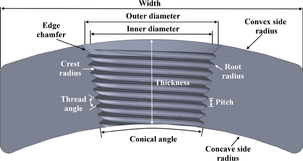
Fig. 1
Design variables of the locking plate.
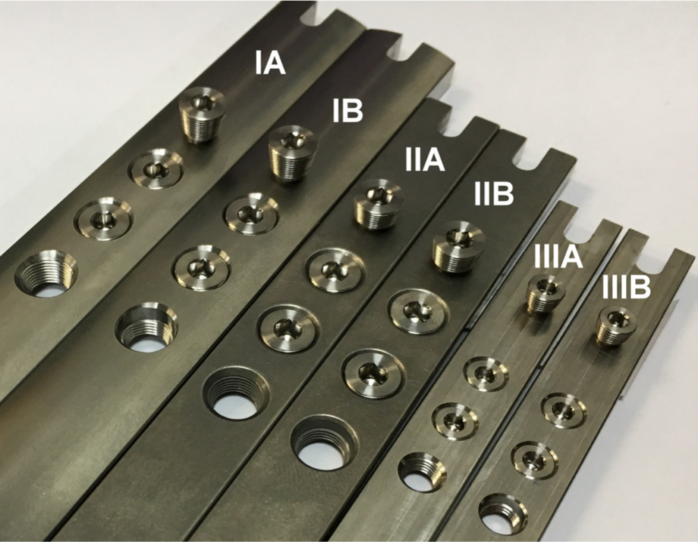
Fig. 2
Configurations of the three types of plates.
Table II.
Dimensions of the screw holes and threads.
| Plate type | Outer diameter, mm | Inner diameter, mm | Conical angle, ° | Crest radius, mm | Root radius, mm | Pitch, mm | Thread angle, ° |
|---|---|---|---|---|---|---|---|
| Type I | 8 | 7.28 | 20 | 0.05 | 0.05 | 0.5 | 60 |
| Type II | 8 | 7.28 | 20 | 0.05 | 0.05 | 0.5 | 60 |
| Type III | 5.5 | 4.64 | 18 | 0.05 | 0.05 | 0.5 | 60 |
-
The thread structures were consistent with those of commercial plates (Zimmer, Warsaw, Indiana, USA).
Plate mechanical tests
Four-point bending tests as per the American Society and Testing Materials (ASTM) F382-14 standards were conducted on the locking plates to simulate worst-case scenario clinical conditions using a servo-hydraulic material testing machine (Instron 8872; Instron Industrial Products, Grove City, Pennsylvania, USA) (Figure 3a). The plates under test were supported by two outer metal rollers with 120 mm, 100 mm, and 80 mm spans for the type I, II, and III plates, respectively, and the loading was applied at the centre of each plate using two inner metal rollers with 60 mm, 50 mm, and 40 mm spans, respectively. The plates were prevented from moving during the cyclic loading tests by two bars inserted into the slots at the ends of the plates.3,9 In this experiment, according to the torques suggested in the operation instructions of the commercial locking plates, the screw heads were inserted orthogonally into the screw holes on the type I, II, and III plates with maximum torques of 4 Nm, 4 Nm, and 2 Nm, respectively, using a torque limited driver. Firstly, three plates of each type were tested to determine the stiffness and yield strength using a single ramp type load at a loading rate of 1 mm per minute in displacement control mode. The loading was continued until the plates were permanently deformed, and the tests were terminated when the displacement of the actuator reached 6 mm. Then, with the same test setup, ten new plates of each type were tested with sinusoidal cyclic loading at a rate of 10 Hz using a fatigue-rated load cell. The maximum load applied during cyclic loading was estimated from a previous study,3 and the stress ratio between the minimum and maximum loads was 10%. The plates were loaded cyclically to failure until cracks were visible. The fatigue life, which was defined as the total number of loading cycles at failure, was recorded along with the cyclic stiffness. Afterward, the fracture surfaces of the failed plates were investigated under an optical microscope (EVM-S2515; Resson Technologies, New Taipei, Taiwan).
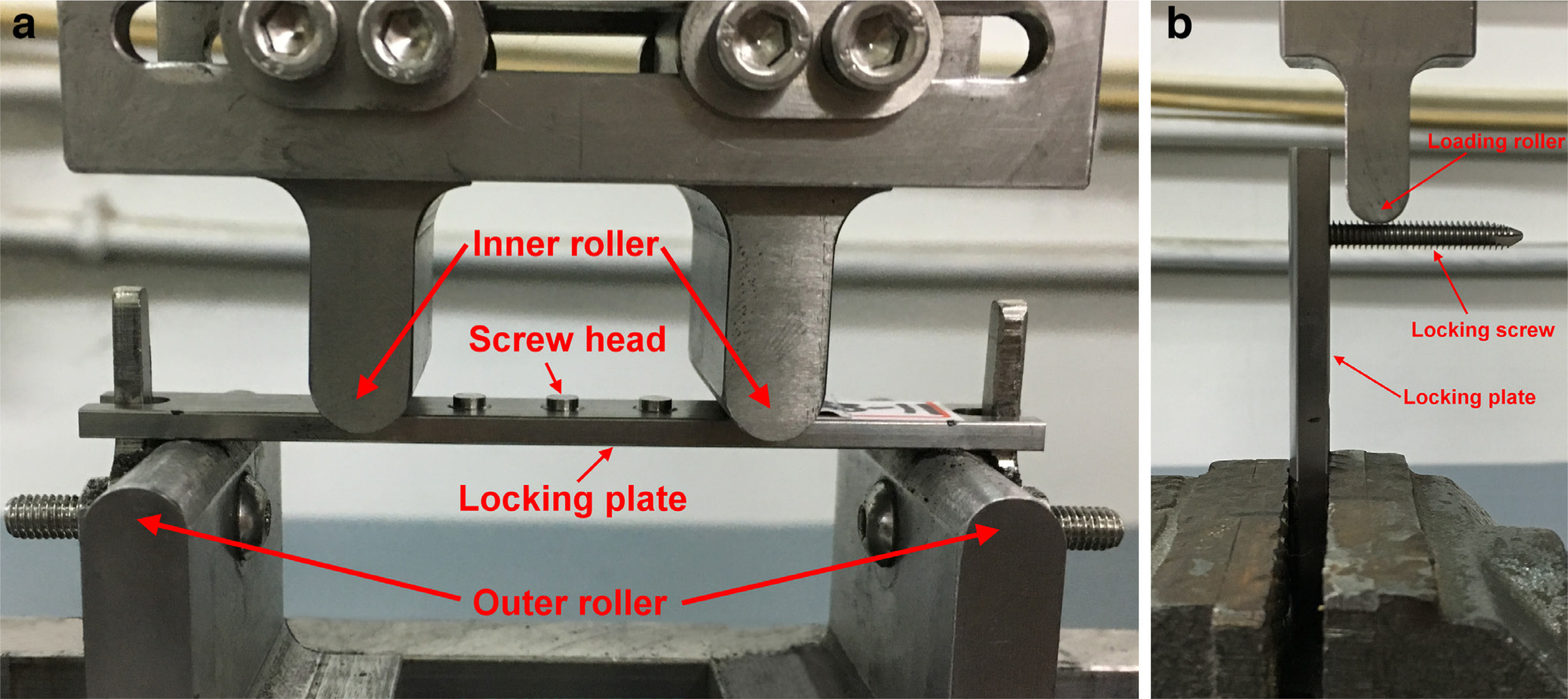
Fig. 3
a) Test setups for the four-point bending tests. b) Test setups for the screw bending tests.
Screw stability (removal and bending) tests
Firstly, the tightness of the screw heads was evaluated by measuring the removal torque before and after the cyclic loading of the plates. The removal torques were manually measured with a torque wrench (KANON N12TOK-G; Nakamura Mfg. Co. Ltd., Tokyo, Japan) by using a technique similar to that employed in clinical implant removal operations performed by ordinary surgeons. After cyclic loading, the removal torques were also measured on both intact and broken holes. Secondly, the holding power of the screw threads was measured via bending tests (Figure 3b). The locking screws were applied to the plates after cyclic loading tests using the same method as that employed during the fatigue testing. Then, the type I, II, and III plates were secured in a vice with distances of 37.5 mm, 27.5 mm, and 18.25 mm, respectively, between the screw and the fixture, and a vertical load was applied to the screw shaft at an offset distance of 10 mm from the plate. The screws were loaded to failure (permanent deformation) at a loading rate of 1 mm per minute. The highest load on the load–deformation curve was taken as the bending strength of the screw threads. For the screw removal tests, 20 different samples were used before cycling loading. After cyclic loading, 20 with intact holes and ten with broken holes were utilized. For the screw bending tests, ten different new screws were used.
Statistical analysis
Analysis of variance (ANOVA) with unequal variance (SPSS v22.0; IBM, Armonk, New York, USA) was used to compare the differences between the A and B plates for each parameter. A significant difference was defined as p < 0.05. The normality of the data distribution was checked by Kolmogorov–Smirnov tests. Post hoc power analyses based on an expected effect size with clinical importance were performed when statistically non-significant results were obtained (G*Power 3.1; Heinrich-Heine-Universität Düsseldorf, Düsseldorf, Germany).
Results
Plate mechanical tests
The stiffness and yield strength, defined as in ASTM F382-14, of the A and B plates was very similar (Table III), although the cyclic stiffness was generally higher than the static loading stiffness. To ensure plate breakage at the end of the tests, the maximum loads in the cyclic loading were 2,100 N, 1,300 N, and 1,000 N (Supplementary Table i) for plate types I, II, and III, respectively, corresponding to 39.2%, 58.0%, and 70.3% of the yield loads. High loads were applied in these tests to simulate the worst-case scenario and guarantee failure. All of the plates cracked at the lateral edges of the screw holes with fracture surfaces perpendicular to the longitudinal axes of the plates. The fracture surfaces were flat with a small marginal lip. All of the plates failed at either of the two side holes, except for two that failed at the middle holes (the type IIA and IIIB plates). The half-threaded plates exhibited fatigue lives 11.9, 16.3, and 11.4 × 10³ cycles significantly (p < 0.01 for all by ANOVA) longer than those of the plates with full threads for plate types I, II, and III, respectively (Figure 4) (Supplementary Table ii and Supplementary Figure b). When observed under an optical microscope, the cracks began at the chamfer or the first thread in all of the plates. However, four of the type IIB plates and eight of the type IIIB plates had additional cracks in the thread region. More thread deformation was observed in the half-threaded holes, especially for types II and III. This might indicate that the half-threaded holes were more highly loaded than the fully threaded holes because of the lower thread number. However, it might also be caused by more loading cycles (Supplementary Figure c).
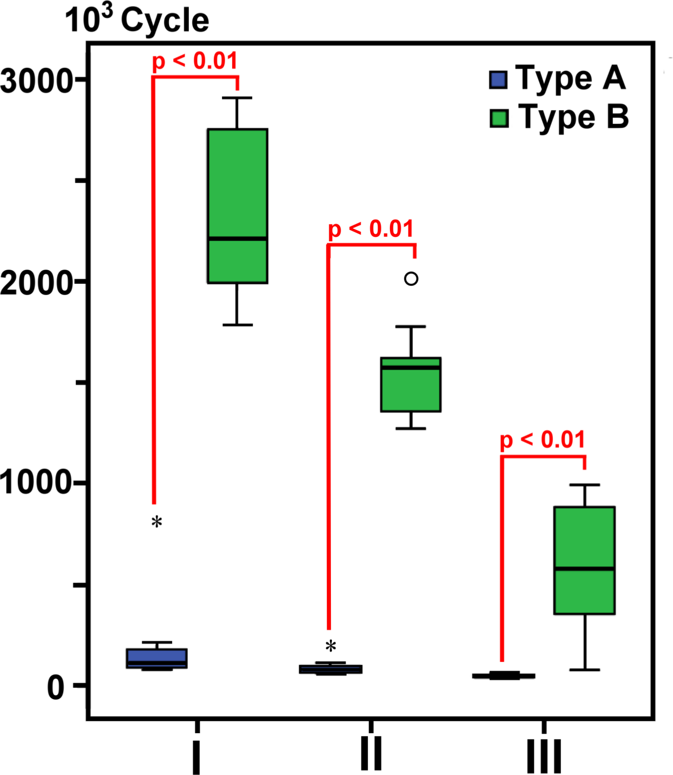
Fig. 4
Box plot of the fatigue life. The asterisks denote the extreme values in the three box lengths from either end of the box. The small circles denote the outliers between one-and-a-half and three box lengths from either end of the box. The statistical test used was analysis of variance.
Table III.
Strengths of the plates.
| Testing result | Sample number |
IA | IB | IIA | IIB | IIIA | IIIB |
|---|---|---|---|---|---|---|---|
| Mean stiffness, N/mm (SD) | 3 | 1,315.2 (9.4) | 1,289.3 (1.7) | 731.9 (6.8) | 752.8 (13.1) | 485.5 (15.3) | 516.4 (2.1) |
| Mean yield load, N (SD) | 3 | 5,360.8 (27.0) | 5,569.7 (13.1) | 2,223.2 (67.7) | 2,257.7 (16.4) | 1,406.4 (21.4) | 1,438.6 (24.0) |
| Mean cyclic stiffness, N/mm (SD) | 3 | 1,640.2 (34.6) | 1,621.8 (31.7) | 836.9 (25.2) | 859.3 (25.1) | 798.1 (28.0) | 828.7 (23.9) |
| Mean fatigue life, 103 cycles (SD) | 10 | 193.2 (211.2) | 2,307.0 (388.7)* | 96.1(39.2) | 1,561.0 (209.6)* | 52.1 (8.1) | 595.9 (29.6)* |
-
*
Statistically significant values between the A and B plates.
Screw stability (removal and bending) tests
Before cyclic loading, the removal torques for all of the plates were higher than the insertion torques (5.3% vs 9.5%, 4.3% vs 9.3%, and 5% vs 1.5% for the A and B plates of types I, II, and III, respectively) (Table IV). In the type I and II plates, the removal torques for the B plates were significantly higher than those for the A plates (p = 0.012 and p < 0.01 by ANOVA, respectively) (Figure 5a). However, in the type III plates, the removal torque for the B plates was significantly lower than that for the A plates (p = 0.023 by ANOVA) (Supplementary Table iii). For the plates with intact holes after cyclic loading, the removal torques were slightly lower than the insertion torques for all but the type IB plates (7.8% vs 0%, 17.3% vs 7.5%, and 11% vs 16.5% for the A and B plates of types I, II, and III, respectively) (Supplementary Table iv). In the type I and II plates, the removal torques for the B plates were significantly higher than those for the A plates (p < 0.01 for both by ANOVA), although the type IIIB plates exhibited a much larger decrease than the type IIIA plates (p = 0.03 by ANOVA) (Figure 5b). For the broken holes, the removal torques were much lower than those for the intact holes and were not significantly different between the A and B plates for all three plate types (Supplementary Table v). In the bending strength tests, all of the screws angulated at the head shaft junction with fractures in the type I and II plates (Supplementary Figure d and Supplementary Table vi); however, the maximum loads at failure were not significantly different between the A and B plates for any of the types (Table IV). For power analyses, to detect a difference of 7.5% with ten samples in each group at a significance level of 0.05, the power was 0.99, 0.99, and 0.91 for plate types I, II, and III, respectively, in the screw bending tests, and 0.12, 0.08, and 0.09 for plate types I, II, and III, respectively, in the screw removal tests.
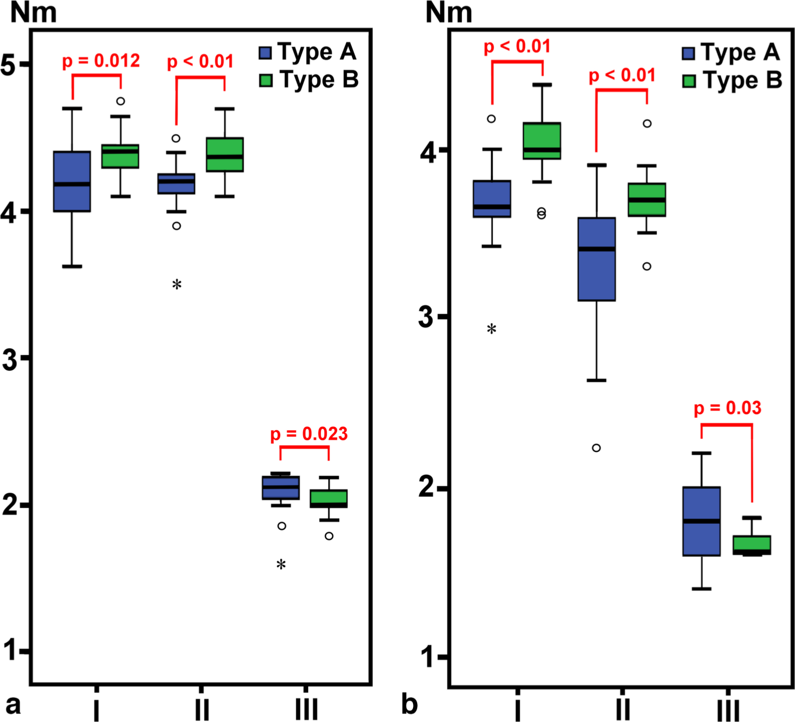
Fig. 5
a) Box plot of the removal torque before cyclic loading. b) Box plot of the removal torque after cyclic loading. The statistical test used was analysis of variance. Asterisks denote the extreme values and the small circles denote the outliers.
Table IV.
Removal torques and bending strengths of the screws.
| Testing result | Sample number | IA | IB | IIA | IIB | IIIA | IIIB |
|---|---|---|---|---|---|---|---|
| Mean removal torque before cyclic loading, Nm (SD) | 20 | 4.21 (0.25) | 4.38* (0.17) | 4.17 (0.19) | 4.37* (0.15) | 2.10 (0.13) | 2.03* (0.08) |
| Mean removal torque after cyclic loading, Nm (SD) | |||||||
| Intact holes | 20 | 3.69 (0.23) | 4.01* (0.18) | 3.37 (0.41) | 3.70* (0.16) | 1.78 (0.21) | 1.67* (0.07) |
| Broken holes | 10 | 0.49 (0.19) | 0.35 (0.17) | 1.25 (1.04) | 1.52 (0.66) | 1.07 (0.69) | 0.88 (0.34) |
| Mean bending load, N (SD) | 10 | 925.3 (15.3) | 935.7 (13.2) | 962.4 (41.2) | 951.7 (24.2) | 750.2 (40.6) | 763.3 (31.0) |
-
*
Statistically significant values between the A and B plates.
Discussion
The notch sensitivity effect of titanium is particularly pronounced at the surface of an implant containing marks or notches, such as those in spinal rods contoured by French benders11 or at locations with abrupt geometrical changes,12 including the holes for locking nails10 and the screw threads in locking plates.9 This notch sensitivity has not been comprehensively investigated in the literature thus far and is still not adequately appreciated by surgeons.11
Although it is known that notch effects may vary substantially among implant designs owing to the stress concentration factors in certain circumstances,10 these effects have not been quantified by researchers to date. Empirically, a notch effect can be characterized by the fatigue notch factor Kf, which is the ratio of the fatigue life of a smooth specimen to that of a notched specimen.13 Although Kf is difficult to determine because it is affected in complex ways by the material, structures, loading magnitude, loading direction, loading rate, etc.9,14 the use of test methods together with empirical models can improve understanding of the problem and provide greater insight toward expanding the test results to similar cases.
For non-locked plates with smooth screw holes, the fatigue strength of titanium devices is much greater than that of 316 L stainless steel.9 Conversely, in locked plates with threaded screw holes, the fatigue strength of titanium devices is much lower than that of 316 L stainless steel because of the notch sensitivity.9,15 However, if the threads are partially removed from the tension side of a titanium plate, then the fatigue strength of the plate can be restored.3 It has also been found that removing half of the threads is more effective than removing one-third of the threads. As noted in the present report, the stiffness and yield strength of the A and B plates was very similar because the influence of the threads was negligible. The cyclic stiffness was higher than the single-load stiffness because of the higher loading rate. As mentioned, removing half of the threads significantly increased the fatigue life by approximately 11– to 16-times in the three types of plates. When a load was applied, all but two of the plates cracked at the side holes, due to the stress-relieving effects16 that resulted in higher stress at the side holes. In a previous study in which finite element analysis was employed, the difference in the maximum stress between the plates with full and partial threads was small.9 The screw hole threads caused very small stress concentration effects because the loading on the threads was not actually mode I, which denotes crack opening under a normal tensile stress perpendicular to the crack.9,17 However, the threads could still induce substantial notch effects on the fatigue lives of the plates. Optical microscope observations revealed that the cracks began at the chamfer or the first thread in all of the plates, as the bending load caused the highest stress on the tension side of each plate. The chamfer could reduce the plate stress and increase the fatigue life.9 However, additional cracks appeared in the thread regions of four of the type IIB plates and eight of the type IIIB plates. Along with the findings of a previous study that cracks can be initiated in the thread region of the plates upon removal of one-third of the threads,3 it was postulated that the distance between the threads and tension surface could also determine the notch effects. Therefore, it may be possible to improve further the fatigue lives of the type IIB and IIIB plates, in which the threads were closer to the tension surface with even fewer threads. However, further improvement of the fatigue lives of the type IB plates may not be possible, as the distance has already plateaued.
Clinically, it is uncommon for locking screws to loosen18 because the metal-to-metal contact between the screw head and plate is more reliable than metal-to-bone contact. However, once the screws loosen, the fixation stability may be severely jeopardized and could lead to fractural nonunion. Common causes of screw loosening include improper screw tightening, unicortical purchase, and off-axis insertion.19,20 However, decreasing the thread count, as proposed in the current study, may also jeopardize the screw plate bonding and cause loosening. In the literature, two methods have been used to assess the stability of locking screws.19,21,22 The first involved measuring the removal torque of the screws before or after cyclic loading, and the second involved the bending strength of the screws. In the former method, the tightness of the screws is assessed as a prerequisite to maintaining the screw holding power, whereas in the latter approach, the screw holding power required to support the bone under load is utilized. The removal torque tended to be higher than the insertion torque before cyclic loading,22 although it could be lower afterwards.23 In the present study, the thread counts for the fully threaded plates were approximately ten, eight, and six, and those for the half-threaded plates were five, four, and three for plate types I, II, and III, respectively. Note, however, that the numbers of threads were not actually integers, as the threads formed conical spirals and could vary on different sides of the screw holes. The higher removal torques before cyclic loading were caused by the abrupt increase in the torque required to loosen the screws during manual screw removal. A higher screw turning speed may increase the removal torque owing to viscoelastic effects. For the plates with intact holes after cyclic loading, the removal torques tended to be lower than the insertion torques (82.7% to 100%). Generally, the type I and II plates had lesser torque decreases than the type III plates because fine threads tend to resist vibration loosening compared to coarse threads.24 It was surmised that the removal torque may also be affected by the screw size, thread structure, insertion torque, loading magnitude, loading cycle number, etc. In the present study, tens or hundreds of thousands of cycles, reflecting the conditions of low cycle fatigue and high loading magnitude, represented the worst-case scenario. The study results indicated that the tightness of the screw heads with only half threads could be maintained in all three plate types. In the screw bending tests, the differences between the A and B plates of the three types were not significant, which indicates that the half threads may exhibit holding power as high as that of full threads. The power analyses indicated that the sample size was sufficient to avoid false negative results. It can also be inferred that three threads may be enough to ensure adequate stability in all types of locking plates. Clinically, certain factors such as long duration, young patient age, screws with 3.5 mm diameter, etc. may be associated with a high risk of screw jamming or even cold welding, which could lead to difficult removal.25 However, the half-threaded design proposed in the present study may decrease screw plate bonding and facilitate screw removal.
Several limitations were identified in the present study. First, the four-point bending test adopted in the present study might not represent real-world physiological conditions, such as those of bone–plate constructs. However, the test method was selected as it complied with the ASTM standards, which have been recognized by the Food and Drug Administration (FDA) as applicable to metallic bone plates for orthopaedic use26 and may also simulate the worst-case scenario. Second, the titanium devices tended to exhibit lower fatigue lives at high loading frequencies.27 However, in the present study high loading frequencies and magnitudes were used to simulate the worst-case scenario. Although the results may vary for different loading rates, loading magnitudes, plate structures, and/or thread designs, the relationship might not change. Third, in the present study cyclic plate bending instead of screw bending was used to investigate the removal torque of the screws after cyclic loading. Clinically, locking screws tend to loosen at fracture sites because the screws are difficult to secure there. Thus, plate bending may be more responsible for screw head toggling in plate holes. Fourth, the present study still cannot explain the relationship between the notch sensitivity effects and plate design. Fifth, the screw stability test results might also have been affected by the number and structure of the threads. Thus, for fair comparison, biomechanical studies should provide details of the thread designs. Last, extending the findings of the present work to other plate/screw designs and loading regimes should also consider the use of the implants in different body parts and different loading conditions, such as rotational or combined loadings.
In conclusion, without affecting the structural stiffness, removing half of the threads from screw holes could markedly increase the fatigue lives of locking plates while preserving the tightness of the screw heads after cyclic loading, as well as the holding power of the locking screws. Partial threads may provide additional advantages by eliminating difficulties in screw removal. However, the effects of the loading rate, loading magnitude, and thread design on the fatigue lives of titanium plates warrant further studies.
References
1. Ehlinger M , Adam P , Arlettaz Y , et al. Minimally-invasive fixation of distal extra-articular femur fractures with locking plates: limitations and failures . Orthop Traumatol Surg Res . 2011 ; 97 ( 6 ): 668 – 674 . Crossref PubMed Google Scholar
2. Piétu G , Ehlinger M . Minimally invasive internal fixation of distal femur fractures . Orthop Traumatol Surg Res . 2017 ; 103 ( 1S ): S161 – S169 . Crossref PubMed Google Scholar
3. Lin C-H , Chao C-K , Ho Y-J , Lin J . Modification of the screw hole structures to improve the fatigue strength of locking plates . Clin Biomech . 2018 ; 54 : 71 – 77 . Crossref PubMed Google Scholar
4. Gardner MJ , Evans JM , Dunbar RP . Failure of fracture plate fixation . J Am Acad Orthop Surg . 2009 ; 17 ( 10 ): 647 – 657 . Crossref PubMed Google Scholar
5. Strauss EJ , Schwarzkopf R , Kummer F , Egol KA . The current status of locked plating: the good, the bad, and the ugly . J Orthop Trauma . 2008 ; 22 ( 7 ): 479 – 486 . Crossref PubMed Google Scholar
6. Smith WR , Ziran BH , Anglen JO , Stahel PF . Locking plates: tips and tricks . J Bone Joint Surg Am . 2007 ; 89-A ( 10 ): 2298 – 2307 . PubMed Google Scholar
7. Henderson CE , Kuhl LL , Fitzpatrick DC , Marsh JL . Locking plates for distal femur fractures: is there a problem with fracture healing? J Orthop Trauma . 2011 ; 25 Suppl 1 : S8 – S14 . Crossref PubMed Google Scholar
8. MacLeod AR , Serrancoli G , Fregly BJ , Toms AD , Gill HS . The effect of plate design, bridging span, and fracture healing on the performance of high tibial osteotomy plates: an experimental and finite element study . Bone Joint Res . 2018 ; 7 ( 12 ): 639 – 649 . Crossref PubMed Google Scholar
9. Tseng W-J , Chao C-K , Wang C-C , Lin J . Notch sensitivity jeopardizes titanium locking plate fatigue strength . Injury . 2016 ; 47 ( 12 ): 2726 – 2732 . Crossref PubMed Google Scholar
10. Hsu C-C , Yongyut A , Chao C-K , Lin J . Notch sensitivity of titanium causing contradictory effects on locked nails and screws . Med Eng Phys . 2010 ; 32 ( 5 ): 454 – 460 . Crossref PubMed Google Scholar
11. Dick JC , Bourgeault CA . Notch sensitivity of titanium alloy, commercially pure titanium, and stainless steel spinal implants . Spine . 2001 ; 26 ( 15 ): 1668 – 1672 . Crossref PubMed Google Scholar
12. Chen P-Q , Lin S-J , Wu S-S , So H . Mechanical performance of the new posterior spinal implant: effect of materials, connecting plate, and pedicle screw design . Spine . 2003 ; 28 ( 9 ): 881 – 886 . Crossref PubMed Google Scholar
13. Haritos G , Nicholas T , Lanning DB . Notch size effects in HCF behavior of Ti–6Al–4V . Int J Fatigue . 1999 ; 21 ( 7 ): 643 – 652 . Google Scholar
14. Yao W , Xia K , Gu Y . On the fatigue Notch factor, Kf . Int J Fatigue . 1995 ; 17 ( 4 ): 245 – 251 . Google Scholar
15. Hung L-W , Chao C-K , Huang J-R , Lin J . Screw head plugs increase the fatigue strength of stainless steel, but not of titanium, locking plates . Bone Joint Res . 2018 ; 7 ( 12 ): 629 – 635 . Google Scholar
16. Noda N-A , Matsuo T . Singular integral equation method in optimization of stress-relieving hole: a new approach based on the body force method . Int J Fract . 1995 ; 70 ( 2 ): 147 – 165 . Google Scholar
17. Livieri P . A new path independent integral applied to notched components under mode I loadings . Int J Fract . 2003 ; 123 ( 3/4 ): 107 – 125 . Google Scholar
18. Kääb MJ , Frenk A , Schmeling A , et al. Locked internal fixator: sensitivity of screw/plate stability to the correct insertion angle of the screw . J Orthop Trauma . 2004 ; 18 ( 8 ): 483 – 487 . Crossref PubMed Google Scholar
19. Gallagher B , Silva MJ , Ricci WM . Effect of off-axis screw insertion, insertion torque, and plate contouring on locked screw strength . J Orthop Trauma . 2014 ; 28 ( 7 ): 427 – 432 . Crossref PubMed Google Scholar
20. Gueorguiev B , Lenz M . Why and how do locking plates fail? Injury . 2018 ; 49 Suppl 1 : S56 – S60 . Crossref PubMed Google Scholar
21. Lenz M , Wahl D , Gueorguiev B , Jupiter JB , Perren SM . Concept of variable angle locking--evolution and mechanical evaluation of a recent technology . J Orthop Res . 2015 ; 33 ( 7 ): 988 – 992 . Crossref PubMed Google Scholar
22. Lenz M , Wahl D , Zderic I , et al. Head-locking durability of fixed and variable angle locking screws under repetitive loading . J Orthop Res . 2016 ; 34 ( 6 ): 949 – 952 . Crossref PubMed Google Scholar
23. Sandriesser S , Rupp M , Greinwald M , et al. Locking design affects the jamming of screws in locking plates . Injury . 2018 ; 49 Suppl 1 : S61 – S65 . Crossref PubMed Google Scholar
24. No authors listed . Coarse threads vs. fine threads . KATOpedia . 2020 . http://www.katonet.com/article/coarsevsfine.html (date last accessed 10 September 2020 ). Google Scholar
25. Lin C-H , Chao C-K , Tang Y-H , Lin J . Improving socket design to prevent difficult removal of locking screws . Injury . 2018 ; 49 ( 3 ): 585 – 592 . Crossref PubMed Google Scholar
26. Lin ASP , Fechter CM , Magill M , et al. The effect of contouring on fatigue resistance of three types of fracture fixation plates . J Orthop Surg Res . 2016 ; 11 ( 1 ): 107 . Crossref PubMed Google Scholar
27. Stambough JL , Genaidy AM , Huston RL , et al. Biomechanical assessment of titanium and stainless steel posterior spinal constructs: effects of absolute/relative loading and frequency on fatigue life and determination of failure modes . J Spinal Disord . 1997 ; 10 ( 6 ): 473 – 481 . PubMed Google Scholar
Author contributions
C-K. Chao: Performed the experiments, Collected the data, Drafted and revised the manuscript.
Y-L. Chen: Conducted the experiments, Collected the data, Revised the manuscript.
J. Lin: Designed the study, Performed the experiments, Collected the data, Drafted and revised the manuscript, Wrote the grant applications.
Funding statement
This work was supported by the Ministry of Science and Technology, Taiwan, ROC (107-2221-E-002-051-MY2). No benefits in any form have been received or will be received from a commercial party related directly or indirectly to the subject of this article.
Supplementary material
Tables show the estimation of the maximum load used for fatigue tests and detailed results for all the mechanical tests. Figures illustrate the geometries of the screw holes of both plate types, the cycle-displacement curves in four-point bending tests, the cross sections of the plates at the cracked site, and the load-deformation curves in screw stability tests.
© 2020 Author(s) et al. This is an open-access article distributed under the terms of the Creative Commons Attribution Non-Commercial No Derivatives (CC BY-NC-ND 4.0) licence, which permits the copying and redistribution of the work only, and provided the original author and source are credited. See https://creativecommons.org/licenses/by-nc-nd/4.0/.
