


Abstract
Objectives
Initial stability of tibial trays is crucial for long-term success of total knee arthroplasty (TKA) in both primary and revision settings. Rotating platform (RP) designs reduce torque transfer at the tibiofemoral interface. We asked if this reduced torque transfer in RP designs resulted in subsequently reduced micromotion at the cemented fixation interface between the prosthesis component and the adjacent bone.
Methods
Composite tibias were implanted with fixed and RP primary and revision tibial trays and biomechanically tested under up to 2.5 kN of axial compression and 10° of external femoral component rotation. Relative micromotion between the implanted tibial tray and the neighbouring bone was quantified using high-precision digital image correlation techniques.
Results
Rotational malalignment between femoral and tibial components generated 40% less overall tibial tray micromotion in RP designs than in standard fixed bearing tibial trays. RP trays reduced micromotion by up to 172 µm in axial compression and 84 µm in rotational malalignment models.
Conclusions
Reduced torque transfer at the tibiofemoral interface in RP tibial trays reduces relative component micromotion and may aid long-term stability in cases of revision TKA or poor bone quality.
Cite this article: Mr S. R. Small. Micromotion at the tibial plateau in primary and revision total knee arthroplasty: fixed versus rotating platform designs. Bone Joint Res 2016;5:122–129. DOI: 10.1302/2046-3758.54.2000481.
Article focus
-
An investigation of tibial component stability as it relates to femoral and tibial component malalignment in total knee arthroplasty (TKA).
-
Establishment of a methodology to assess movement at the bone-implant interface using three-dimensional digital image correlation.
Key messages
-
Rotating platform tibial components generate reduced implant micromotion by lessening tibiofemoral torque transfer.
Strengths and limitations
-
The study is the first to implement non-contact digital image correlation methodologies to quantify three-dimensional micromotion between the tibial tray and neighbouring bone in a TKA model.
-
This study is limited in that it uses composite tibial specimens in a simplified loading scenario in order to assess difference in stability of fixed and rotating platform component designs.
Introduction
Cemented total knee arthroplasty (TKA) has been a highly successful elective procedure, with excellent long-term survivorship in several different device designs.1-9 Polyethylene wear resulting in osteolysis and aseptic loosening is a common, multifactorial, late-term failure mechanism in cemented arthroplasty. Micromotion at the cement-implant and cement-bone interfaces may contribute to this failure mechanism through predisposition to focal osteolysis and the enabling of polyethylene wear debris to migrate into the bone distally.10,11 Because adequate initial stability of cemented TKA tibial prostheses contributes to long-term success of the implant, several prior studies focused on increased stability through cementing technique and surface preparation.11-16 Fewer studies have investigated the role of device design in improving implant stability in cemented tibial trays.
Tibial component micromotion is a mechanical result of the combination of shear forces and moments at the tibiofemoral joint generated during the complex biomechanics at the knee during gait. Mobile-bearing tibial components were introduced in the late 1970s in order to decouple the shear moments generated by rotation between femoral and tibial components during knee flexion.17 These designs enable high articular conformity and decreased polyethylene contact stress, reducing articular wear in addition to reducing post damage in constrained condylar and posterior stabilised designs.18-22 Previous studies have documented reduced torque transfer from femoral component rotation and malalignment at the tibiofemoral articulation with mobile bearing designs, subsequently reducing torsion-induced strain across the proximal tibia.23,24 The reduction of torsion-induced strain during knee loading following mobile-bearing TKA may decrease excessive loading at the bone-cement and cement-prosthesis interface, thus reducing the rate of interface fatigue.
Understanding the mechanical implications of rotation at the knee as a result of flexion or rotational malalignment is crucial for maximising component stability and promoting durable implant-cement-bone interfaces, particularly during revision TKA. Prior studies have described reduced torque transfer and cortical tibial strain in tibias implanted with rotating platform (RP) mobile-bearing tray designs.23,24 We therefore asked if the RP TKA designs result in improved tibial tray stability and decreased component micromotion in both the primary and revision settings.
Materials and Methods
In this study, relative micromotion was measured within tibial specimens implanted with one of four prosthesis designs: fixed-bearing, posterior stabilised primary components (PFC Sigma, DePuy Orthopaedics Inc., Warsaw, Indiana); RP, posterior stabilised primary components (PFC Sigma, DePuy Orthopaedics, Inc.); fixed-bearing, posterior stabilised revision components with 115 mm × 14 mm press-fit distal stem and reduced intercondylar width (PFC TC3, DePuy Orthopaedics Inc.); and RP, posterior stabilised revision components with 75 mm × 14 mm press-fit distal stem and reduced intercondylar width (PFC TC3, DePuy Orthopaedics Inc.). All tibial trays were manufacturer ‘Size 3’ with 10 mm thick polyethylene bearings. Fourth generation composite tibial specimens (Medium, Left, Model 3401, Pacific Research Laboratories, Vashon, Washington) were chosen as the test specimen for their reduced interspecimen variability as compared with cadaveric tissue.25,26 All tibial components were implanted by a board certified orthopaedic surgeon (RAM) using standard instrumentation and high-viscosity polymethylmethacrylate (PMMC) bone cement (SmartSet HV, DePuy Orthopaedics Inc.) following the manufacturer’s suggested surgical technique of 0° of posterior slope and surgeon preference of neutral varus-valgus alignment based on the long axis of the composite tibia.
Primary tibial components were fully cemented along the baseplate and stem, while revision components utilised press-fit fixation in the distal stem, with proximal cementing limited to the underside of the tibial tray. Cement was finger-packed to both the component and tibial plateau and manually impacted. Full tibial tray seating was attained in all specimens and visually verified by the implanting surgeon. A total of six tibial specimens were implanted per experimental group.
Biomechanical testing was conducted on a biaxial electrodynamic materials testing machine (ElectroPuls E10,000 A/T, Instron, Norwood, Massachusetts). Specimens were incorporated into the materials testing machine via a custom fixture allowing free medial/lateral and anterior/posterior translation of the potted base. Femoral components selected to match tibial component size and design (PFC Sigma and PFC T3 Size 3, DePuy Orthopaedics, Inc.), were integrated into the upper testing grips to allow for repeatable load application through the femoral component onto the polyethylene bearing surface at the lowest preferred dwell point. A silicon-based lubricant (DM-Fluid-350CS, Shin-Etsu Chemical Co, Tokyo, Japan) was applied between all articulating surfaces to lubricate the otherwise dry in vitro test environment. Testing was conducted in two phases: compressive loading ramped at a rate of 60 N/s to a peak load of 2.5 kN, followed by femoral component rotation at a rate of 0.5 degrees per second to a final position of 10° external tibiofemoral malalignment. In all instances the femoral component was positioned in 90° of flexion. A total of five trials were repeated for each of four digital image correlation (DIC) viewing angles (anterior, medial, posterior, and lateral) in all 24 specimens, with micromotion data collected as the change in position of each data point between the start and completion of each testing phase.
DIC was used in this study to provide non-contact micromotion analysis with greater precision than alternative techniques, namely linear variable displacement transducers (LVDTs). A set of two calibrated, high resolution cameras with 50 mm lenses (5M, GOM Inc., Braunschweig, Germany) were used in conjunction with the ARAMIS 5.0 software suite (GOM Inc.) to perform DIC displacement analysis through surface pattern matching across a series of images during testing. The paired cameras were fixed on a single tripod at a 20° angle relative to each other, 400 mm apart and at a distance of 1 m from the test specimen. In preparation for optical pattern matching analysis, a thin basecoat of white paint was applied to the proximal tibial cortex and the peripheral rim of the tibial tray. A fine black speckle pattern was then painted over the primed surface to generate a pattern tuned to the specifications of the DIC system manufacturer template (Fig. 1). A post hoc speckle analysis using a custom MATLAB program (Mathworks, Inc., Natick, Massachusetts) showed a mean speckle size of 0.04 mm2. During each loading sequence (no load, compression only, compression with rotation) image data was collected in a 160 mm × 135 mm × 120 mm calibrated 3D field of view. Because DIC is a line-of-sight measurement technique, trials were repeated in each anterior, medial, posterior and lateral view in order to capture data at all regions of interest around the periphery of the proximal tibia and tibial tray. Following testing, measurement points on the tibial tray were paired with partner points within close proximity to the tray on the proximal tibial cortex in each of the anterior, medial, lateral, posteromedial and posterolateral measurement regions. To calculate micromotion, a line was drawn between each corresponding pair of measurement points within the DIC software package. The 3D change in length of this line over time was tracked throughout the loading cycle via ARAMIS 5.0 digital image correlation software (GOM, Inc.). Coordinate data of the line was exported from the digital image correlation software package and analysed in a custom programmed MATLAB algorithm (MATLAB R2010b, Mathworks, Inc.).

Fig. 1
A finely distributed black and white speckle pattern applied to the tibia cortex and the outer rim of the tibial tray. (Right) Three dimensional surface mapping via digital image correlation software allowing spatial tracking of bone and metal reference points.
To address the repeated measurements taken on the bone specimens, generalised estimating equations (GEE) were used to estimate a marginal linear model for the mean micromotion; a separate model was considered for the axial and torsional tests. For each model, a compound symmetric structure was specified for the working correlation matrix. The primary analysis considered the effects of the component design, bearing mobility, and measurement region. The effect of the component design was allowed to depend on the bearing mobility. A secondary analysis was conducted to make comparisons of individual measurement regions. The primary models above were altered to allow the effects of design and the bearing mobility to depend on the measurement region, creating a fully saturated model. All pairwise comparisons were then estimated. All analyses were conducted in R version 3.2.2 (2015-08-14). The generalised estimating equations were fit using the geepack package (version 1.2.0).
Results
Micromotion analysis was conducted in two stages of joint loading: axial compression and rotational malalignment. Tibial component micromotion generated as a result of axial compression is presented in Figure 2 with statistical comparisons between device designs presented in Tables I and II. Across all bones and measurement regions, the average repeatability within each bone and measurement region subset of data was 74 µm in axial testing. From this data there is no evidence that the overall axial compression micromotion is dependent upon the primary versus revision component design (p = 0.845), however, the model suggests that, on average, the axial compression micromotion is somewhat related to bearing mobility (p = 0.055) and is strongly associated with the measurement region (p < 0.001). A statistically significant difference between fixed and RP tibial component designs was observed in two measurement regions in the primary component design, with the fixed bearing primary tray exhibiting significantly higher micromotion in the medial (+ 66 µm, p = 0.042) and posteromedial (+ 67 µm, p = 0.035) measurement regions. Likewise, a 172 µm (p < 0.001) greater micromotion was observed in the lateral measurement region of the fixed bearing components when comparing bearing mobility within the revision component design.
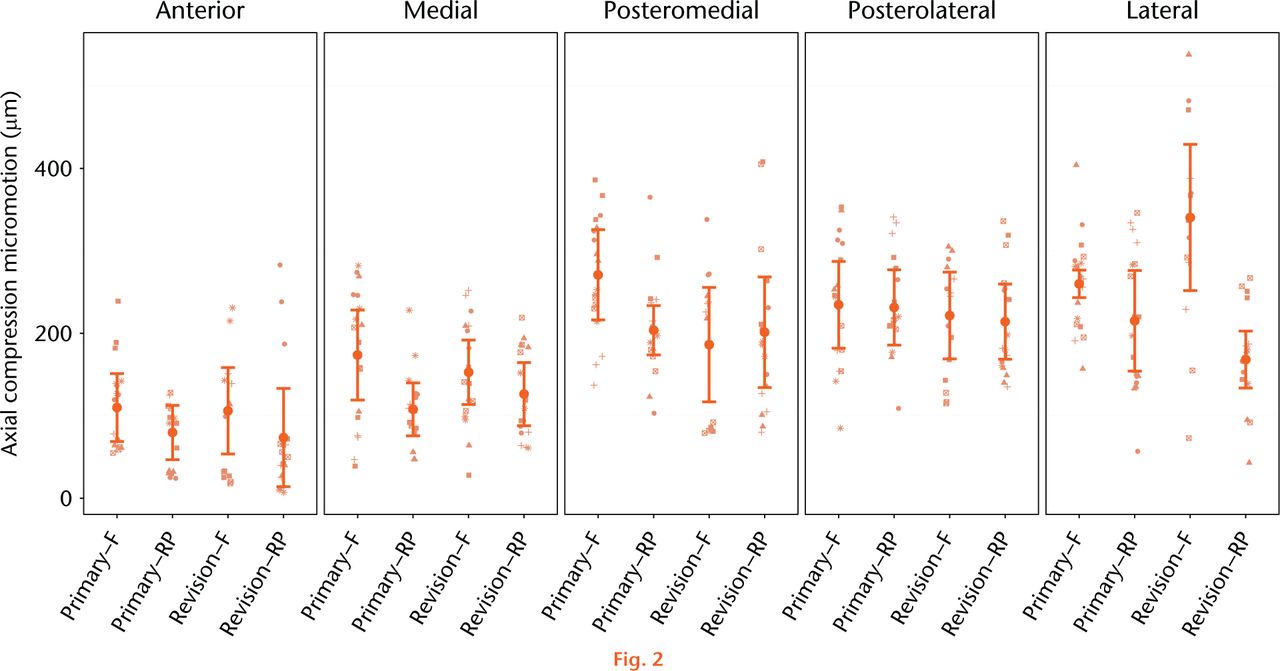
Fig. 2
Mean relative micromotion between implanted tibial tray and the composite tibia specimen as a result of 2.5 kN axial compression. The estimated mean micromotion and associated 95% confidence intervals (CI) are included. Symbols are used to link measurements associated with the same bone within the group of interest. (F, Fixed; RP, rotating platform).
Table I.
Comparisons of mean micromotion (µm, (95% confidence interval)), response in axial compression: fixed vs mobile.
| Region | Fixed | RP | p-value | |
|---|---|---|---|---|
| Primary | Anterior | 110 (69 to 179) | 80 (47 to 113) | 0.259 |
| Medial | 174 (119 to 229) | 108 (76 to 140) | 0.042 | |
| Posteromedial | 271 (216 to 326) | 204 (174 to 234) | 0.035 | |
| Posterolateral | 235 (182 to 288) | 231 (185 to 277) | 0.927 | |
| Lateral | 260 (243 to 277) | 215 (154 to 276) | 0.165 | |
| Revision | Anterior | 106 (54 to 158) | 74 (14 to 134) | 0.423 |
| Medial | 153 (117 to 192) | 126 (88 to 164) | 0.344 | |
| Posteromedial | 186 (117 to 255) | 201 (134 to 268) | 0.760 | |
| Posterolateral | 221 (168 to 274) | 214 (168 to 260) | 0.834 | |
| Lateral | 340 (251 to 429) | 168 (133 to 203) | < 0.001 |
-
p-value from pairwise comparison
-
RP, rotating platform
Table II.
Comparisons of mean micromotion (µm, (95% confidence interval)), response in axial compression: primary vs revision.
| Region | Primary | Revision | p-value | |
|---|---|---|---|---|
| Fixed | Anterior | 110 (69 to 179) | 106 (54 to 158) | 0.907 |
| Medial | 174 (119 to 229) | 153 (117 to 192) | 0.542 | |
| Posteromedial | 271 (216 to 326) | 186 (117 to 255) | 0.060 | |
| Posterolateral | 235 (182 to 288) | 221 (168 to 274) | 0.732 | |
| Lateral | 260 (243 to 277) | 340 (251 to 429) | 0.080 | |
| RP | Anterior | 80 (47 to 113) | 74 (14 to 134) | 0.862 |
| Medial | 108 (76 to 140) | 126 (88 to 164) | 0.469 | |
| Posteromedial | 204 (174 to 234) | 201 (134 to 268) | 0.947 | |
| Posterolateral | 231 (185 to 277) | 214 (168 to 260) | 0.601 | |
| Lateral | 215 (154 to 276) | 168 (133 to 203) | 0.189 |
-
p-value from pairwise comparison
Tibial component micromotion generated as a result of rotational malalignment between the tibial and femoral components is presented in Figure 3 with statistical comparisons presented in Tables III and IV. Across all bones and measurement regions, the average repeatability within each bone and measurement region subset of data was 41 µm in rotational malalignment testing. The rotational malalignment model suggests tibial tray micromotion is dependent upon primary versus revision component design (p = 0.001), bearing mobility (p < 0.001), and the measurement region (p < 0.001). Furthermore, there is evidence that the effect of the component design is dependent upon the bearing mobility (p = 0.018). Specifically, for fixed bearing devices, the micromotion for revised components tends to be 42 µm greater than that for primary components. However, for RP devices, the micromotion for revision components tents to be only 9 µm greater than that for primary components. So, the RP design appears to dampen the impact of moving from a primary to a revision component design. Under torsional loading as a result of rotational malalignment, the fixed bearing primary tray exhibited significantly higher micromotion than the primary RP tray in the medial (+62 µm, p < 0.001) and lateral regions (+10 µm, p = 0.013). Rotational malalignment in the revision tibial trays resulted in higher micromotion in the fixed bearing trays at the anterior (+84 µm, p < 0.001), medial (+82 µm, p < 0.001), posterolateral (+59 µm, p < 0.001) and lateral (+45 µm, p < 0.001) measurement regions. When directly comparing rotation-induced micromotion between primary and revision tibial trays, the revision fixed bearing tray exhibited 78 µm (p < 0.001) and 42 µm (p < 0.001) higher micromotion than the primary fixed bearing tray in the posterolateral and lateral regions, respectively. The revision RP tray exhibited 18 µm (p = 0.033) higher micromotion than the primary RP tray in the medial measurement region.
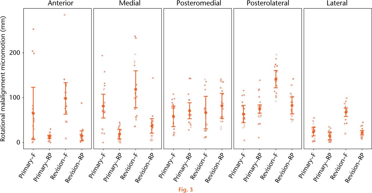
Fig. 3
Mean relative micromotion between implanted tibial tray and the composite tibia specimen as a result of 10° femoral component rotation. The estimated mean micromotion and associated 95% confidence intervals are included. Symbols are used to link measurements associated with the same bone within the group of interest. (F, Fixed; RP, rotating platform).
Table III.
Comparisons of mean micromotion (µm, (95% confidence interval)) response in rotational malalignment: fixed vs mobile.
| Region | Fixed | RP | p-value | |
|---|---|---|---|---|
| Primary | Anterior | 65 (7 to 123) | 13 (9 to 17) | 0.078 |
| Medial | 81 (54 to 108) | 19 (8 to 30) | < 0.001 | |
| Posteromedial | 59 (36 to 82] | 71 (53 to 89) | 0.401 | |
| Posterolateral | 64 (45 to 83) | 75 (66 to 84) | 0.301 | |
| Lateral | 25 (15 to 35) | 15 (7 to 23) | 0.013 | |
| Revision | Anterior | 99 (64 to 134) | 15 (6 to 24) | < 0.001 |
| Medial | 119 (78 to 160) | 37 (21 to 53) | < 0.001 | |
| Posteromedial | 67 (31 to 103) | 82 (54 to 110) | 0.519 | |
| Posterolateral | 142 (123 to 161) | 83 (64 to 102) | < 0.001 | |
| Lateral | 67 (31 to 103) | 22 (17 to 27) | < 0.001 |
-
p-value from pairwise comparison
-
RP, rotating platform
Table IV.
Comparisons of mean micromotion (µm (95% confidence intervals) response in rotational malalignment: primary vs revision.
| Region | Primary | Revision | p-value | |
|---|---|---|---|---|
| Fixed | Anterior | 65 (7 to 123) | 99 (64 to 134) | 0.335 |
| Medial | 81 (54 to 108) | 119 (78 to 160) | 0.134 | |
| Posteromedial | 59 (36 to 82) | 67 (31 to 103) | 0.705 | |
| Posterolateral | 64 (45 to 83) | 142 (123 to 161) | < 0.001 | |
| Lateral | 25 (15 to 35) | 67 (31 to 103) | < 0.001 | |
| RP | Anterior | 13 (9 to 17) | 15 (6 to 24) | 0.678 |
| Medial | 19 (8 to 30) | 37 (21 to 53) | 0.065 | |
| Posteromedial | 71 (53 to 89) | 82 (54 to 110) | 0.519 | |
| Posterolateral | 75 (66 to 84) | 83 (64 to 102) | 0.464 | |
| Lateral | 15 (7 to 23) | 22 (17 to 27) | 0.145 |
-
p-value from pairwise comparison
-
RP, rotating platform
Discussion
The vastly different mechanics of RP and fixed bearing tibial trays are a result of the manufacturers’ aim to decouple motion and constraint at the tibiofemoral interface. RP designs result in decreased torque transfer through the prosthesis at the joint articulation and decreased torsional strain response in the proximal tibia as a result of tibiofemoral rotation during gait or due to component malrotation. While component micromotion is most commonly studied in cementless applications, component stability is critical for long-term clinical success in cemented TKA as well. Therefore, this study was designed to compare the relative stability of cemented, fixed and RP tibial tray designs in both the primary and the more highly constrained revision scenario.
Rotational malalignment between the femoral and tibial components in TKA of over 10º has been described in up to 12% of TKA cases,27 and has been clinically associated with persistent pain and early revision.28-31 Previous studies have observed torsional loads between 8.2 Nm to 16.9 Nm as a result of 10° of malrotation in fixed bearing tray designs with a reduction of 68% to 91% reduction in torque in mobile-bearing versions of the tibial tray23,24,32 The current study demonstrated a significant reduction in component micromotion as a result of the reduced torque transfer in the RP designs. Micromotion as a result of interface torque due to rotational malalignment in fixed bearing TKA designs were a mean of 79 microns (25 to 142) across all measurement regions, compared with a mean of 43 microns (13 to 83) across all measurement regions in RP designs. Overall an average 40% reduction in torque-induced component micromotion was observed with the RP designs. Additionally, the RP design exhibited reduced micromotion when compared with the fixed bearing designs during the direct axial compression phase of the loading cycle in two primary and one revision measurement region. This difference in compressive stability was unexpected and perhaps reflects some unrecognised bias in the methodology.
Micromotion has historically been measured in biomechanical models as a means to quantify stability of an implant in both cemented and cementless orthopaedic applications. Prior studies have utilised fixed and intrusive electromechanical transducers for single-axis measurement or computational methods for estimated micromotion analysis.33-39 The introduction of digital image correlation technologies into biomechanical research has allowed for non-contact optical measurement of the relative displacement between implant and bone in three dimensions with high accuracy and resolution for increased measurement ease and expanded research applications. For example, in a recent study, Mann et al40 used DIC to assess micromotion in tibial components in postmortem retrieval specimens and reported a measurement error of 1.1 µm using similar point-to-point techniques as the current study. Additionally, we established a measurement uncertainty of 3.4 µm of the system and methodology used in the current study during micromotion analysis in a total hip arthroplasty model.41 That uncertainty measurement was made by comparing point-to-point change in displacement between a fixed and translated baseplate across an 8 mm gage length as measured by both DIC and linear variable displacement transducer (LVDT) methods.41
Because rigid initial fixation is essential for proper bone ingrowth and long-term survivorship in porous coated devices, most TKA biomechanical micromotion studies have focused on the assessment of uncemented tibial trays. Far fewer studies have focused on the stability and micromotion in cemented components as the degree of micromotion is less critical in the short-term following cemented TKA. Nevertheless, the use of PMMC bone cement remains the current standard in TKA fixation, and as such, adequate fixation of the tibial baseplate and minimisation of interface fatigue is essential for the reduced risk of aseptic loosening in the large population of cemented-TKA patients.
Micromotion analysis of the cemented TKA has been used to compare the inherent stability of cementation techniques.33-35 In a cadaveric biomechanical study, Peters et al33 measured tibial tray micromotion to compare full versus surface cementation in cruciate and I-beam stem designs. In four measurement regions around the tibial plateau, Peters et al33 reported linear micromotion ranging between 2 microns and 20 microns in a liftoff model and found no difference in stability between cementing techniques. Conversely, Luring et al34 observed increased liftoff micromotion, ranging from 3 microns to 29 microns, with hybrid fixation in comparison with a fully cemented tibial tray in a composite tibia model. In an early study, Sala, Taylor and Tanner35 compared initial torsional stability in press-fit, press-fit with supplemental screw fixation, and horizontally cemented tibial trays in a cadaveric model. In that study, reduced micromotion was observed with cemented fixation, most notably during phases of high torque and low axial load, and in specimens with poor bone quality. In good quality bone, mean torsion-induced micromotion ranged from 25 microns to 73 microns in press-fit trays, 24 microns to 49 microns in trays with supplemental screw fixation, and 21 microns to 35 microns in cemented trays. However, in poor quality bone, micromotion exceeded 350 microns in the press-fit trays and exceeded 150 microns in the cemented tray. In the current study, we observed significantly different stability characteristics between RP and fixed bearing tibial trays in both the primary and revision settings. Higher torsion-induced micromotion (20 microns to 141 microns) and compression-induced micromotion (72 microns to 331 microns) are likely the result of higher testing loads, as well as the comparison of three-dimensional micromotion as measured by DIC as compared with linear micromotion as measured by physical electromechanical transducers.
The authors acknowledge limitations in the methodology of this study which may affect the clinical extrapolation of the data. While manufactured tibia specimens have been validated to exhibit similar material properties to cadaveric tissue, with decreased interspecimen variability, these bone models are a broad simplification of the natural physiological system: lacking soft tissue interactions, bony remodeling, and natural kinematics. Composite specimens were chosen in order to minimise specimen variability in the experimental set-up and ensure prosthesis design as the single primary variable of interest. Additionally, a simplified loading pattern was used in testing which does not fully represent the complex biomechanics produced during gait. Recent studies have shown that greatest micromotion in TKA is observed during periods of low axial load, whereas in this study a full axial load of 2.5 kN was used during micromotion measurement.35-37 This loading profile is artificial and may not reflect the actual in vivo performance of the knee, but was chosen in this study as it allows for the relative comparison of micromotion between the device designs in a controlled manner. The significant differences observed between fixed and RP devices in this loading scenario would perhaps be amplified with lower axial loads. While most knee function occurs at much less femoral flexion, a femoral component position of 90° flexion was chosen as this setup resulted in the highest induced torque in a prior analysis of this design,24 and because this is the range of flexion wherein the femoral component begins interaction with the tibial post. In the current study the primary tibial trays were fully cemented, while revision systems were proximally cemented with press-fit stems. Primary stability in TKA is inherently sensitive to cementation procedure, thus alterations in the cementing and press-fit techniques in these components will invariably change the micromotion response of the trays under physiological loading. Additionally, the relatively small sample size in each experimental group limits the statistical methodology available for establishing the distribution of the data. Furthermore, there was no robust method established to determine the effect of repeated tests required to capture line-of-sight measurements at the five different regions of interest. Ideally, simultaneous data capture from multiple cameras used in stereo would eliminate the need for repeated tests in order to capture data from all measurement points.
In conclusion, relative dynamic stability of the implanted tibial tray in TKA is substantially influenced by tibial tray design. Considerable micromotion as a result of knee joint torque was observed in fixed bearing designs and in more highly constrained revision prostheses. Decoupling of joint torque at the tibial tray through a RP bearing affords increased implant stability as a result of relative tibiofemoral rotation either through gait or due to suboptimal component alignment. The results of this study demonstrate, in a benchtop model, the significant reduction of component micromotion within the RP tray design. Despite this theoretical advantage of tray design, no difference in long-term performance has been established in the literature between fixed and mobile-bearing designs.42 Concerns remain regarding the potential of backside wear associated with the introduction of an additional bearing surface in mobile-bearing trays. Because of this, further work is needed to evaluate the clinical efficacy of the mobile-bearing TKA, particularly in scenarios of poor bone stock and revision arthroplasty, in which micromotion and interface fatigue in cemented designs may play a greater role in long-term survivorship.
Supplementary material
Figures showing experimental set up and micromotion measurement regions are available alongside the online version of this article at www.bjr.boneandjoint.org.uk
Funding Statement
Funding has been received from DePuy Synthes by the JRSI Foundation to offset study costs.
Funding has also been received from the National Science Foundation (Grants #0923135 and #1039716) by Rose-Hulman Institute of Technology for the purchase of instrumentation used in this study.
R. Malinzak reports funding received from Arthrex, Biomet and DePuy, none of which is related to this article.
S. Small reports funding received from Biomet, DePuy, Exactech, Stryker and Orthalign, none of which is related to this article.
M. Ritter reports funding received from Biomet, DePuy, Exactech and Stryker, none of which is related to this article.
ICMJE conflict of interest
K. Farley reports that “While I was an undergraduate at the time of this study, I am now a product development engineering in the shoulder/extremities department of DePuy Orthopaedics.”
References
1 Kim YH , KimJS, ChoeJW, KimHJ. Long-term comparison of fixed-bearing and mobile-bearing total knee replacements in patients younger than fifty-one years of age with osteoarthritis. J Bone Joint Surg [Am]2012;94-A:866-873.CrossrefPubMed Google Scholar
2 Kim YH , YoonSH, KimJS. The long-term results of simultaneous fixed-bearing and mobile-bearing total knee replacements performed in the same patient. J Bone Joint Surg [Br]2007;89-B:1317-1323.CrossrefPubMed Google Scholar
3 Callaghan JJ , WellsCW, LiuSS, GoetzDD, JohnstonRC. Cemented rotating-platform total knee replacement: a concise follow-up, at a minimum of twenty years, of a previous report. J Bone Joint Surg [Am]2010;92-A:1635-1639.CrossrefPubMed Google Scholar
4 Ritter MA . The Anatomic Graduated Component Total Knee Replacement: A Long-Term Evaluation with 20-year Survival Analysis. J Bone Joint Surg. 2009;91-B:745-749. Google Scholar
5 Rodriguez JA , BhendeH, RanawatCS. Total condylar knee replacement: a 20-year followup study. Clin Orthop Relat Res2001;388:10-17.PubMed Google Scholar
6 Vessely MB , WhaleyAL, HarmsenWS, SchleckWSCD, BerryD. J. Long-term Survivorship and Failure Modes of 1000 Cemented Condylar Total Knee Arthroplasties. Clin Orthop Relat Res2006;452:28-34. Google Scholar
7 Carothers JT , KimRH, DennisDA, SouthworthC. Mobile-bearing total knee arthroplasty: a meta-analysis. J Arthroplasty2011;26:537-542.CrossrefPubMed Google Scholar
8 Hopley CDJ , CrossettLS, ChenAF. Long-term clinical outcomes and survivorship after total knee arthroplasty using a rotating platform knee prosthesis: a meta-analysis. J Arthroplasty2013;28:68-77.e1, 3.CrossrefPubMed Google Scholar
9 Tarkin IS , BridgemanJT, JardonOM, GarvinKL. Successful biologic fixation with mobile-bearing total knee arthroplasty. J Arthroplasty2005;20:481-486.CrossrefPubMed Google Scholar
10 Jacobs JJ , ShanbhagA, GlantTT, BlackJ, GalanteJO. Wear Debris in Total Joint Replacements. J Am Acad Orthop Surg1994;2:212-220.CrossrefPubMed Google Scholar
11 Vanlommel J , LuyckxJPJr, LabeyL, et al.. Cemented the Tibial Component in Total Knee Arthroplasty. J Arthroplasty2011;26:492-496. Google Scholar
12 Schlegel UJ , SieweJ, DelankKS, et al.. Pulsed lavage improves fixation strength of cemented tibial components. Int Orthop2011;35:1165-1169.CrossrefPubMed Google Scholar
13 Schlegel UJ , PüschelK, MorlockMM, NagelK. An in vitro comparison of tibial tray cementation using gun pressurization or pulsed lavage. Int Orthop2014;38:967-971.CrossrefPubMed Google Scholar
14 Miskovsky C , WhitesideLA, WhiteSE. The cemented unicondylar knee arthroplasty. An in vitro comparison of three cement techniques. Clin Orthop Relat Res1992;284:215-220.PubMed Google Scholar
15 Bert JM , McShaneM. Is it necessary to cement the tibial stem in cemented total knee arthroplasty?Clin Orthop Relat Res1998;356:73-78.CrossrefPubMed Google Scholar
16 Walker PS , SoudryM, EwaldFC, McVickarH. Control of cement penetration in total knee arthroplasty. Clin Orthop Relat Res1984;185:155-164.PubMed Google Scholar
17 Callaghan JJ , SquireMW, GoetzDD, SullivanPM, JohnstonRC. Cemented Rotating-Platform Total Knee Replacement. J Bone Joint Surg [Am]2000;82-A:705-711.CrossrefPubMed Google Scholar
18 Fisher J , McEwenH, TipperJ, GalvinAL, IngramJ, KamaliA, StoneMH, InghamE. Wear, Debris, and Biologic Activity of Cross-linked Polyethylene in the Knee: Benefits and Potential Concerns. Clin Orthop Relat Res2004;428:114-119.CrossrefPubMed Google Scholar
19 Fisher J , McEwenH, TipperJ, GalvinAL, IngramJ, KamaliA, StoneMH, InghamE. Wear-simulation Analysis of Rotating-platform Mobile-Bearing Knees. Orthopedics2006;29(9 Suppl):S36-41.PubMed Google Scholar
20 Goldstein WM , GordonAC, SwopeS, BransonJ. Rotating Platform Revision Total Knee Arthroplasty. J Knee Surg2012; 25(1):45-50.CrossrefPubMed Google Scholar
21 Currier JH , MayorMB, CollierJP, CurrierBH, Van CrittersDW. Wear Rate in a Series of Retrieved RP Knee Bearings. Journal of ASTM International2011;8(3):10. Google Scholar
22 Puloski SK , McCaldenRW, MacDonaldSJ, RorabeckCH, BourneRB. Tibial Post Wear in Posterior-Stabilized Total Knee Arthroplasty: An Unrecognized Source of Polyethylene Debris. J Bone Joint Surg [Am]2001;83-A:390-397. Google Scholar
23 Bottlang M , ErneOK, LacatusuE, SommersMB, KesslerO. A mobile-bearing knee prosthesis can reduce strain at the proximal tibia. Clin Orthop Relat Res2006;447:105-111.CrossrefPubMed Google Scholar
24 Malinzak RA , SmallSR, RoggeRD, et al.. The effect of rotating platform TKA on strain distribution and torque transmission on the proximal tibia. J Arthroplasty2014;29:541-547.CrossrefPubMed Google Scholar
25 Cristofolini L , VicecontiM. Mechanical validation of whole bone composite tibia models. J Biomech2000;33:279-288.CrossrefPubMed Google Scholar
26 Heiner AD . Structural properties of fourth-generation composite femurs and tibias. J Biomech2008;41:3282-3284.CrossrefPubMed Google Scholar
27 Uehara K , KadoyaY, KobayashiA, OhashiH, YamanoY. Bone anatomy and rotational alignment in total knee arthroplasty. Clin Orthop Relat Res2002;402:196-201.PubMed Google Scholar
28 Arima J , WhitesideLA, McCarthyDS, WhiteSE. Femoral rotational alignment, based on the anteroposterior axis, in total knee arthroplasty in a valgus knee. A technical note. J Bone Joint Surg [Am]1995;77-A:1331-1334.CrossrefPubMed Google Scholar
29 Barrack RL , SchraderT, BertotAJ, WolfeMW, MyersL. Component rotation and anterior knee pain after total knee arthroplasty. Clin Orthop Relat Res2001;392:46-55.CrossrefPubMed Google Scholar
30 Berger RA , CrossettLS, JacobsJJ, RubashHE. Malrotation causing patellofemoral complications after total knee arthroplasty. Clin Orthop Relat Res1998;356:144-153.CrossrefPubMed Google Scholar
31 Anouchi YS , WhitesideLA, KaiserAD, MillianoMT. The effects of axial rotational alignment of the femoral component on knee stability and patellar tracking in total knee arthroplasty demonstrated on autopsy specimens. Clin Orthop Relat Res1993;287:170-177.PubMed Google Scholar
32 Kessler O , LacatusuE, SommersMB, MayrE, BottlangM. Malrotation in total knee arthroplasty: effect on tibial cortex strain captured by laser-based strain acquisition. Clin Biomech2006;21:603-609.CrossrefPubMed Google Scholar
33 Peters CL , CraigMA, MohrRA, BachusKN. Tibial component fixation with cement: full- versus surface-cementation techniques. Clin Orthop Relat Res2003;409:158-168.CrossrefPubMed Google Scholar
34 Luring C , PerlickL, TrepteC, et al.. Micromotion in cemented rotating platform total knee arthroplasty: cemented tibial stem versus hybrid fixation. Arch Orthop Trauma Surg2006;126:45-48.CrossrefPubMed Google Scholar
35 Sala M , TaylorM, TannerKE. Torsional stability of primary total knee replacement tibial prostheses: a biomechanical study in cadaveric bone. J Arthroplasty1999;14:610-615.CrossrefPubMed Google Scholar
36 Taylor M , BarrettDS, DeffenbaughD. Influence of loading and activity on the primary stability of cementless tibial trays. J Orthop Res2012;30:1362-1368.CrossrefPubMed Google Scholar
37 Chong DYR , HansenUN, AmisAA. Analysis of bone-prosthesis interface micromotion for cementless tibial prosthesis fixation and the influence of loading conditions. J Biomech2010;43:1074-1080.CrossrefPubMed Google Scholar
38 Bhimji S , MeneghiniRM. Micromotion of cementless tibial baseplates under physiological loading conditions. J Arthroplasty2012;27:648-654.CrossrefPubMed Google Scholar
39 Bhimji S , MeneghiniRM. Micromotion of cementless tibial baseplates: keels with adjuvant pegs offer more stability than pegs alone. J Arthroplasty2014;29:1503-1506.CrossrefPubMed Google Scholar
40 Mann KA , MillerMA, GoodheartJR, IzantTH, ClearyRJ. Peri-implant bone strains and micro-motion following in vivo service: a postmortem retrieval study of 22 tibial components from total knee replacements. J Orthop Res2014;32:355-361.CrossrefPubMed Google Scholar
41 Small SR , HensleySE, CookPL, StevensRA, RoggeRD, BerendME. The Effect of Stem Length on Strain and Micromotion in the Proximal Femur Following Total Hip Arthroplasty [abstract]. Proceedings to the Orthopaedic Research Society Annual Meeting, 2015. Google Scholar
42 Moskal JT , CappsSG. Rotating-platform TKA no different from fixed-bearing TKA regarding survivorship or performance: a meta-analysis. Clin Orthop Relat Res2014;472:2185-2193. Google Scholar
