


Abstract
Introduction
Wear of polyethylene inserts plays an important role in failure of total knee replacement and can be monitored in vivo by measuring the minimum joint space width in anteroposterior radiographs. The objective of this retrospective cross-sectional study was to compare the accuracy and precision of a new model-based method with the conventional method by analysing the difference between the minimum joint space width measurements and the actual thickness of retrieved polyethylene tibial inserts.
Method
Before revision, the minimum joint space width values and their locations on the insert were measured in 15 fully weight-bearing radiographs. These measurements were compared with the actual minimum thickness values and locations of the retrieved tibial inserts after revision.
Results
The mean error in the model-based minimum joint space width measurement was significantly smaller than the conventional method for medial condyles (0.50 vs 0.94 mm, p < 0.01) and for lateral condyles (0.06 vs 0.34 mm, p = 0.02). The precision (standard deviation of the error) of the methods was similar (0.84 vs 0.79 mm medially and both 0.46 mm laterally). The distance between the true minimum joint space width locations and the locations from the model-based measurements was less than 10 mm in the medial direction in 12 cases and less in the lateral direction in 13 cases.
Conclusion
The model-based minimum joint space width measurement method is more accurate than the conventional measurement with the same precision.
Cite this article: Bone Joint Res 2014;3:289–96
Article Focus
Comparing the accuracy and precision of two minimum joint space width measurement methods for assessing insert wear in total knee prostheses
Investigating the relationship between locations of the minimum joint space width measurement and minimum insert thickness
Key Messages
Model-based minimum joint space width measurement is more accurate than the conventional measurement
Strengths and Limitations
Comparison with retrieval data delivers the best possible evidence for evaluating the accuracy of minimum joint space width measurements
Validation is done with a range of implant designs and degrees of wear
Limitation: Study is conducted with only 15 samples, due to which only general conclusions can be drawn
Introduction
Polyethylene is used as bearing material in total knee replacements (TKR) and its wear plays an important role in TKR failure.1 Remarkably, standardised (computer-assisted) tools for the in vivo assessment of polyethylene wear in TKR do not exist. Rather, planar radiographs are the medical standard for routine monitoring of TKR performance and they are used to estimate changes in the thickness of polyethylene inserts during clinical follow-up. This thickness is quantified with the minimum joint space width (mJSW), which is the apparent distance between the metal tibial tray and the femoral condyles in standard frontal plane radiographs.2-4 The insert thickness and its change over time can predict TKR failure.5,6 However, the conventional mJSW method is applied to image projections, which are subject to parallax errors that occur when the metal tibial baseplate surface is not aligned with the X-ray beam during sequential radiological assessments. mJSW errors in measurement of up to 2 mm are not exceptional and numerous follow-up visits are required to obtain a reliable estimation of the wear rate.3,7
In our earlier work, a novel model-based method was presented to measure the mJSW in standard anteroposterior radiographs using highly accurate and precise model-based Roentgen stereophotogrammetric analysis (RSA) software.8,9 This method has two advantages over the standard mJSW measurements: the effect of parallax errors is reduced by applying a three-dimensional (3D) reconstruction of the prosthesis components using surface models and it gives insight into both the magnitude and location of the mJSW. For a fixed-bearing prosthesis, in vitro validation showed that the model-based method is superior in accuracy (mean -0.03 mm vs 0.20 mm), precision (standard deviation (sd) = 0.19 mm vs 0.40 mm) absolute error (mean 0.14 mm vs 0.35 mm) compared with the conventional method.8 Thus, this method has the potential to improve the accuracy of mJSW measurements, enabling more accurate detection of wear-related complications and improving the power of clinical studies evaluating differences in wear rates between different TKR designs.
In this retrospective cross-sectional study, the actual minimum insert thickness, measured in 3D laser scan data of retrieved polyethylene tibial inserts, was compared with the mJSW measurements acquired using the model-based and conventional methods applied to weight-bearing pre-revision radiographs. The primary objective was to compare the accuracy and precision of these mJSW measurement methods using the insert thickness measured from TKR retrievals as a ‘gold standard’. The secondary objective was to investigate whether the mJSW location determined in the model-based method corresponds to wear locations evident on the explanted polyethylene inserts.
Materials and Methods
Data
We searched a database of explanted TKRs catalogued in an Implant Retrieval Program previously established with institutional review board approval (clinical protocol number in Germany EK348112009; retrieval analysis protocol number in USA IBC2011-26) and patient-informed consent. Wear scars on polyethylene tibial inserts of 60 fixed-bearing TKRs retrieved from a single clinic (University Hospital Carl Gustav Carus, Dresden) were grossly assessed using optical microscopy to visualise the damage modes and physical touch to detect changes in the articular surface contour. A total of 15 posterior cruciate ligament-retaining TKRs were selected to represent a wide range of articular wear scar sizes and shapes, ensuring that the validation study was meaningful for the extensive wear scar variations that can occur in clinical practice.10
Table I lists clinical information such as the TKR design, duration of in vivo TKR function, the reasons for revision surgery and the grade of the wear scar (mild, moderate or severe). Wear scars were graded as mild if the damage modes visibly disrupted the machine marks on the articular surface without causing a perceptible change in the articular geometry (six TKRs); moderate if the damage modes visibly disrupted the machine marks on the articular surface and the wear scar was tangible when physically touching the articular surface (five TKRs); and severe if there was visibly gross material loss (e.g. delamination) and a notable tactile change in the articular geometry due to gross disruption of the bearing surface (four TKRs).
Table I
Description of the 15 total knee replacements (TKR) used in this study
| Case | TKR design† | Wear degree | TKR lifetime (mths) | Lifetime after radiograph‡ (mths) | Reason for revision |
|---|---|---|---|---|---|
| K2004 | TC-Plus | Mild | 41 | 0.7 | Infection |
| K2133 | TC-Plus | Mild | 17 | 0.2 | Pain |
| K2145 | TC-Plus | Mild | 24 | 3.0 | Infection |
| K2154 | Zimmer NK | Mild | 50 | 12.1 | Infection |
| K2171 | TC-Plus | Mild | 34 | 0.0 | Painful flexion, infection |
| K2178 | TC-Plus | Mild | 19 | 2.5 | Infection |
| K2035* | TC-Plus | Moderate | 23 | 0.0 | Infection |
| K2132 | TC-Plus | Moderate | 86 | 0.2 | Infection |
| K2137 | TC-Plus | Moderate | 130 | 23.6 | Suspected osteolysis later diagnosed as metastasis |
| K2144 | TC-Plus | Moderate | 132 | 3.1 | Aseptic loosening |
| K2175 | TC-Plus | Moderate | 60 | 0.0 | Infection |
| K2046* | Encore foundation | Severe | 144 | 4.0 | Aseptic loosening |
| K2156* | Stryker 7000 | Severe | 77 | 0.2 | Infection |
| K2159* | Sulzer Protek | Severe | 108 | 1.6 | Infection |
| K2161 | TC-Plus | Severe | 108 | 0.2 | Infection |
-
* For these TKRs, double leg standing radiographs were used for measuring mJSW; for all other TKR a single leg standing radiograph was used † List of manufacturers: TC-Plus (Smith & Nephew, London, UK); Zimmer NK (Zimmer, Warsaw, Indiana); Encore Foundation (DJO Surgical, Vista, California); Stryker 7000 (Stryker, Kalamazoo, Michigan); Sulzer Protek (Protek Medical Product Inc., Coralville, Iowa) ‡ The period between the radiograph acquisition and revision surgery
For each TKR, the most recent anteroposterior planar radiograph was selected from those acquired during routine clinical examination prior to the revision surgery. The radiographs were acquired with a Siemens Aristos FX Axiom imaging device (0.143 mm per pixel). All patients were instructed to remain fully weight-bearing on both limbs. The selected radiographs include unilateral (n = 11) and bilateral (n = 4) exposures. The radiographs were transmitted in DICOM format following a de-identification process to protect patient privacy in preparation for the radiological assessments.
Individual 3D surface models (triangulated meshes) of the explanted components (metal tibial baseplate, polyethylene tibial insert, metal femoral component) were generated using reverse engineering software and a 3D laser scanner (Next Engine, Santa Monica, California). These scans had an accuracy of 0.1 mm.
Assessment methods
The mJSW was measured on the pre-revision radiograph using both the conventional (C) and model-based (MB) methods; the true insert thickness (d0) and position (p0) on the medial and lateral compartments were measured from the scanned models of the polyethylene inserts. The details of these assessments are described below and depicted in Figure 1. Last, the articular wear scar on the insert was identified by digitising the periphery of the worn area.
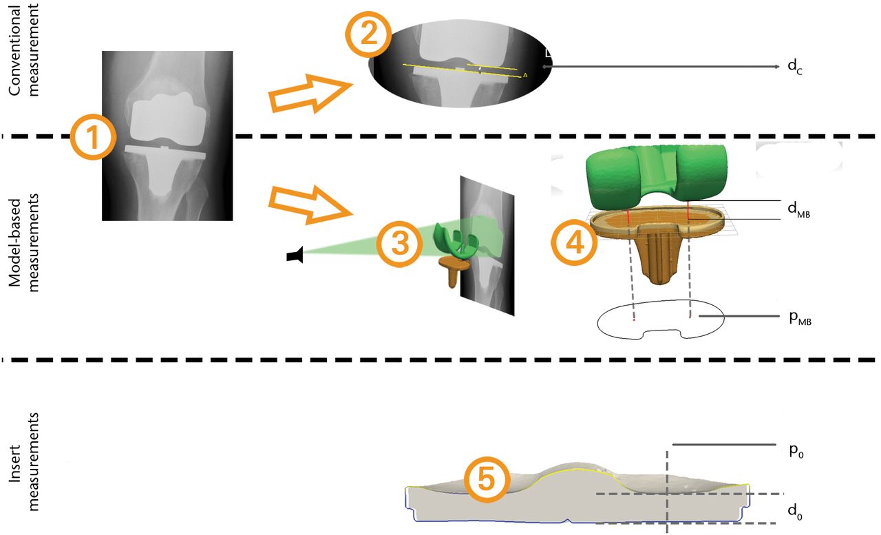
Fig. 1
Overview of the measurement methods applied for a single total knee replacement (TKR). The rows in the figure represent the measurement methods that were compared: 1) the input radiograph; 2) the conventional insert thickness measurement; 3) 2D/3D matching of the component models; 4) model-based mJSW measurement; 5) the minimum insert thickness and location based on the 3D laser scan of the insert.
Conventional mJSW method
In the conventional mJSW method, the insert thickness (dc) was assessed directly in the radiological image, based on the metal-to-middlemethod.7 This assessment was conducted by an experienced orthopaedic surgeon and an experienced researcher (HvdL, EAvIJ) and the mean values of the observations were used in the further analysis. Commercially available software was used (Digimizer, MedCalc Software, Mariakerke, Belgium) for annotation, image processing and measurement of distances. A reference line was drawn that annotated the superior rim of the metal tibial baseplate at its largest medial–lateral width. The shortest, tibiofemoral distances between this line and the distal femoral condylar edges were measured. The tibial component rim is used for the capture mechanisms securing the polyethylene tibial inserts to the metal baseplate. Therefore, the height of the rim above the tibial baseplate surface was measured by one observer (EAvlJ) at three locations using Magics (Materialize, Leuven, Belgium). The mean height was added to the tibiofemoral distances, yielding the final estimate of the insert thickness.
Image magnification was calculated using the ratio between the tibial tray widths in the image silhouette and in the scanned model. This was used to convert all image-based mJSW measurements to real-world dimensions, recorded as the medial dc and lateral dc.
Model-based mJSW method
In the model-based method, the mJSW (dMB) was assessed using triangulated surface models of the components (tibia, insert and femur) and model-based RSA software (Version 3.34, RSAcore, Leiden, The Netherlands).11 The tibial model and the insert model were aligned in such a way that the insert’s inferior surface and the tibial baseplate’s superior surface coincided with the 0 xz-plane of the model coordinate systems.
Assessment of the TKRs was initiated with an image focus calibration step. The pixel size was obtained from the DICOM data and the focus position was set at a distance of 115 cm from the centre of the image, in accordance with the hospital’s imaging protocol. Next, the tibial and femoral models were matched with the radiographs using 2D image/3D model registration.
The mJSW was measured by detecting the femoral condylar model with the shortest distance to the tibial baseplate (dMB). The projection of the points (pMB)was stored and expressed in anterioposterior (AP) and mediolateral (ML) coordinates with respect to the centre of the tibial baseplate. The measurement was repeated by two researchers (EAvIJ and BLK), who independently conducted the registration and measurement processes. The mean values of the observations were used in further analysis.
Insert measurements
Using the 3D laser scan of the explanted polyethylene inserts, the minimum insert thickness in millimetres (d0) was measured as the minimum perpendicular distance between the inferior backside surface and the articular surface of the insert. The scans were aligned with the tibial models and the locations of the minimum insert thickness (p0) were expressed in the same coordinate system as in the model-based mJSW method.
One experienced observer (MKH) analysed the wear scar area of the inserts using the following approach: The wear scar areas were visually identified using an optical stereomicroscope (model Z30L, Cambridge Instruments, Cambridge, Massachusetts). Subsequently, the circumference of both the insert periphery and the wear scars were digitised on calibrated digital images of the articular surface using published photogrammetry methods.12,13 The insert circumference was used to map these data to the tibial model coordinate system.
Statistical analysis
The values ∆C and ∆MB were calculated as the difference between the respective mJSW assessment dC and dMB and the reference insert thickness d0 (∆C = dC – d0, ∆MB = dMB – d0). The mean and sd of these differences over the 15 cases were calculated and compared (paired t-test). In addition, the mean measurement errors were calculated as the mean of the absolute difference ∆C and ∆MB and the number of cases having an absolute difference less than 1 mm was counted, similar to the analysis by Collier et al.7 Inter-observer agreement was analysed with the limits of agreement and Bland–Altman plots per condyle and mJSW measurement method.14
To investigate whether the model-based mJSW measurement can accurately determine the location of the minimum insert thickness, the locations of the model-based mJSW assessment (pMB) and minimum insert thickness (p0) were compared. The accuracy of the mJSW could be associated with the difference in these locations and this was tested by computing the correlation between these outcomes. Absolute error and accuracy were determined based on measurement of calibrated images of shapes with known dimensions. The technique had an absolute error of 0.4 mm for linear distances and 3.5 mm2 for areas and was 98.6% accurate. Precision was 0.4 mm for linear distances and 3.9 mm2 for areas based on repeated measurements taken by one user. The number of TKRs was counted for which the model-based measurement points (pMB) were within the wear scar periphery.
Results
After enduring functional lifetimes of approximately 1.5 to 12 years, the actual minimum insert thickness measured on these explanted polyethylene bearings ranged from d0 = 1.99 mm to 7.86 mm medially and 4.97 mm to 7.92 mm laterally (Fig. 2). The mean difference between the mJSW (dMB or dC) and insert thickness (d0) was positive for both methods (Table II), meaning that both methods tended to overestimate the actual minimum insert thickness that was measured from the explanted tibial inserts. The sd of the mJSW measurement methods was similar. The mean measurement error was significantly smaller for the model-based measurement than for the conventional measurement for both the medial (0.50 mm vs 0.94 mm, p < 0.01) and lateral condyle (0.06 mm vs 0.34 mm, p = 0.02); (paired t-tests).
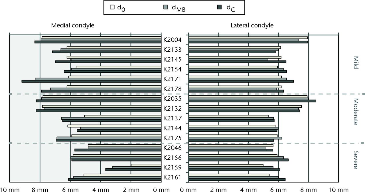
Fig. 2
Barplots of the estimated insert thicknesses dC from the conventional mJSW method, dMB from the model-based mJSW method, and actual minimum insert thickness d0 for each case. The cases are ordered as in Table I and grouped by wear grade.
Table II
Statistics of the differences between the mJSW measurements (conventional ∆C and model-based ∆MB) with respect to the true minimum insert thickness
| Medial condyle (N = 15) | Lateral condyle (N = 15) | ||||||
|---|---|---|---|---|---|---|---|
| ∆C | ∆MB | ∆C | ∆MB | ||||
| Mean (mm) | 0.94 | 0.50 | p = 0.00* | 0.34 | 0.06 | p = 0.02* | |
| Standard deviation (mm) | 0.84 | 0.79 | p = 0.77† | 0.46 | 0.46 | p = 0.98† | |
| Mean measurement error (mm) | 1.02 | 0.66 | p = 0.00* | 0.44 | 0.40 | p = 0.31* | |
| N (err < 1 mm) (%) | 9 (60) | 11 (73) | 13 (87) | 15 (100) | |||
-
* Paired t-test for equal means † Levene’s test for homogeneity of variance
The limits of agreement between the observers over the 15 cases were calculated for both mJSW, measurement methods. For the model-based mJSW, the values were 0.00 (sd 0.45) and 0.00 (sd 0.54) (mean ± 1.96 × sd) for the medial and lateral condyles, respectively. For the conventional mJSW, these values were -0.22 (sd 0.48) and -0.21 (sd 0.45). For both condyles a systematic difference was found between the observers for the conventional method (Student t-test, p < 0.01). The Bland–Altman plots of the outcomes (Fig. 3). The Bland–Altman plots of the outcomes (Fig. 3) showed no other trends for either mJSW measurement method. Two outliers (K2154 and K2156, both condyles) were found in the distribution of the observer difference for the model-based measurement. For the conventional measurement case, a single outlier was found (K2154).


Figs. 3a - 3b
Bland–Altman plots a) of the model-based mJSW and b) of the conventional mJSW method
Evaluation of the measurement points
The locations of the measurement point (pMB) was compared with the minimum insert thickness location (p0) and the wear scar area (Fig. 4) and the wear scar area (Fig. 4) and the difference between the points in terms of AP and ML distance was computed (Table III). The largest distances were found in the AP direction, where the differences ranged between -18 mm (anterior) and +6 mm (posterior). The distance was less than 10 mm for 12 out of 15 cases medially and 13 out of 15 cases laterally. The median distance was 6 mm (1 to 18). For all cases the locations were inside or at the edge of, the wear scar area. No significant correlation was found between the distance and the measurement error of the model-based mJSW measurement (Spearman’s rho = 0.07, p = 0.70).
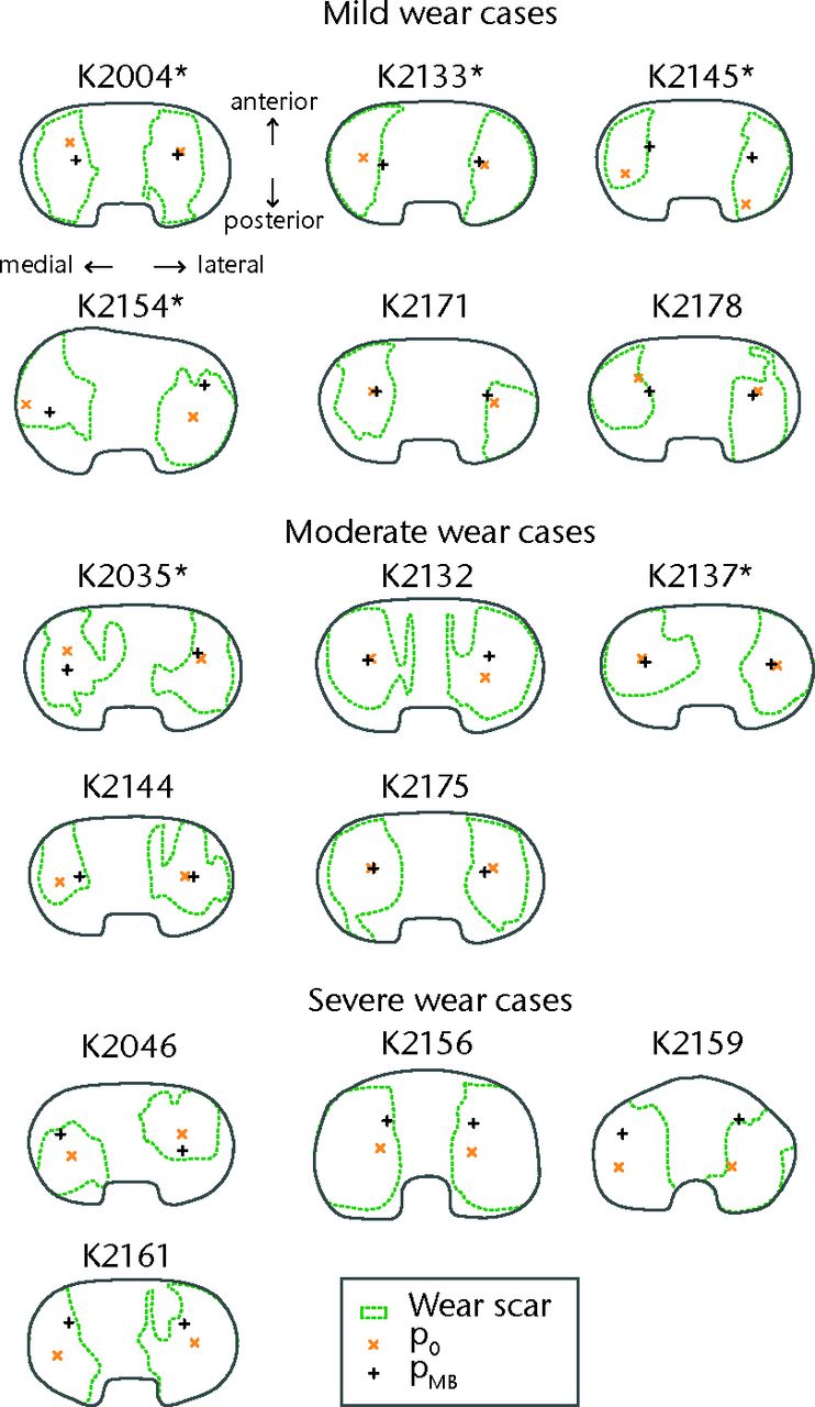
Fig. 4
Illustrations of the articular surfaces of each explanted insert, showing the wear scar peripheries and locations of the minimum insert thickness (p0) and the femoral contact (pMB). These illustrations are plotted as looking down on the superior surface of a right knee, with the medial condyle always at the left side of the image. Illustrations of inserts originating from left TKR are mirrored to fit this convention and are indicated with an asterisk (*) after the case number.
Table III
The differences in position between the femoral contact locations (pMB) and the minimum insert thickness locations (p0) (as seen in Fig. 4). Values are expressed in millimetres.
| Case | Condition | Medial compartment | Lateral compartment | ||
|---|---|---|---|---|---|
| AP difference | ML difference | AP difference | ML difference | ||
| K2004 | Mild | 5.98 | -1.84 | 0.63 | 1.06 |
| K2133 | Mild | 5.98 | -0.22 | -2.06 | 0.81 |
| K2145 | Mild | -7.47 | 3.88 | 5.05 | -0.68 |
| K2154 | Mild | 0.52 | 0.76 | -7.51 | -0.96 |
| K2171 | Mild | 2.02 | -6.38 | -1.29 | 2.26 |
| K2178 | Mild | 1.67 | -1.06 | -0.46 | 1.20 |
| K2035 | Moderate | -1.95 | -7.26 | -0.14 | -3.37 |
| K2132 | Moderate | -8.97 | -8.80 | -16.40 | -2.59 |
| K2137 | Moderate | 2.32 | -6.57 | -8.80 | -3.39 |
| K2144 | Moderate | -9.04 | -2.06 | -9.10 | -0.17 |
| K2175 | Moderate | -12.88 | -1.16 | -17.76 | -2.18 |
| K2046 | Severe | -11.02 | -3.69 | -6.06 | 3.60 |
| K2156 | Severe | 0.14 | -1.07 | -2.51 | 2.42 |
| K2159* | Severe | 0.03 | -0.53 | 1.27 | 1.99 |
| K2161 | Severe | 4.89 | -4.30 | 1.43 | 1.78 |
-
AP, Anterioposterior direction; ML, mediolateral direction
Discussion
The primary objective was to compare the accuracy and precision of the model-based mJSW measurement and the conventional mJSW measurement using minimum insert thickness measured from TKR retrievals as a ‘gold standard’. The accuracy (proximity to the truth) and precision (measurement reproducibility) of both methods were determined by applying the methods to pre-operative radiographs and comparing the outcomes with the minimum thickness of the retrieved inserts. The results showed that the model-based measurement method was more accurate than the conventional method for both condyles (0.50 mm vs 0.94 mm medially and 0.06 mm vs 0.34 mm laterally). The precision of the methods was similar (0.84 mm vs 0.79 mm medially and both 0.46 mm laterally). Both mJSW measurements were more accurate and precise for the lateral condyle than for the medial condyle. Since this occurred for both methods, this is not a measurement error. Apparently a physical difference existed between the femorotibial distance and the insert thickness, which may be related to various clinical conditions such as varus malalignment.
Concerning the observer reproducibility for the model-based method the mean difference was 0.0 mm and for the conventional method the mean difference between the observers was 0.2 mm. The limits of agreements of the mJSW measurement methods were similar. For the cases K2154 and K2156 a large difference (> 0.5 mm) was found between the model-based observers, mJSW measurements. For K2154, some bone cement was still attached to the backside of the tibial baseplate when it was scanned. This introduces a model inaccuracy and complicates the matching procedure, as the respective contours of the tibial metal baseplate should then not be used in the 2D/3D matching. One observer deselected these particular contours, whereas the other observer included this contour part, which may explain the measurement difference. For K2156, one observer did not apply the 2D/3D matching process for the tibial component correctly. This resulted in an out-of-plane positioning error that affected the measurement outcome. Still, the mean measurements for these cases were not remarkably far from the actual minimum insert thickness. The outlier for the conventional mJSW measurement (K2154) was related to a difference in setting the height of the reference line at the tibial baseplate.
Four cases stand out (K2137, K2159, K2171 and K2178) as relatively large overestimations (more than 1 mm) of the medial insert thickness for both methods. For K2137 this seems to be related to the image calibration: in the model-based optimisation the posterior edge of the femoral component models is approximately 3 cm away from the X-ray detector plate, which is physically unlikely. For K2159 there is a large difference between the measurement location, pMB, and the actual minimum insert thickness location, p0. For the other cases no obvious explanation could be found, and it may be possible that for these patients there was no actual contact at the mJSW position pMB at the medial side.
Our secondary objective was to investigate whether the explanted inserts truly show wear scars at the points measured by the model-based mJSW technique. The analysis showed that this was true for all inserts. It should be noted that for some cases, such as K2156 and K2132, the wear scar covers the majority of the inserts’ articular surface area, which dilutes the information of this observation as any measurement is bound to reside in the wear scar area. Still, this finding supports the proposition that the mJSW measurement is suitable to detect wear.
Concerning the difference between the minimum insert thickness location (p0) and the femoral contact location (pMB), the findings were volatile. The findings were similar for the medial and lateral condyles: the Euclidean difference was less than 10 mm for 12 cases medially and 13 cases laterally. When this difference was greater than 10 mm, the measurement point was always more anterior than p0. This could be related to the patient positioning: patients are standing with extended knees during the image acquisition, whereas the femoral condyles reposition during dynamic activities.15 In posterior cruciate ligament-retaining TKR, knee flexion during activity can contribute to posterior contact of the femoral condyles and posterior wear scars.16 This is supported by the observation that three out of four cases with severe wear had a relatively posterior location for p0. The anteroposterior direction also corresponds to the film-focus direction for a frontal plane radiograph, for which the 2D-3D model matching algorithm is the least accurate. The difference in location can therefore also be related to measurement error.
Collier et al7 found that conventional mJSW measurements had an accuracy within 1 mm for 82% medially and 58% laterally. This is comparable to the findings with the conventional method in the current study (60% medially and 87% laterally within 1 mm), although the accuracy numbers for the condyles are interchanged. Differences between these results could be caused by the type of prosthesis that was evaluated. Whereas Collier et al7 used a single, flat-surfaced anatomic modular knee (Depuy, Warsaw, Indiana), the measurements in the current study were applied to five different implant designs to validate our measurement technique as a more generic application to different implant models. This also included designs having a metal rim capture mechanism on the tibial baseplate, which can distort the projection image and for which an alternative approach of the conventional mJSW method had to be used. Moreover, Collier, et al7 achieved good measurement accuracy only when TKR were well aligned relative to the projection plane, necessitating that 28% to 39% of their radiographs be discarded from the measurement analysis due to excessive anteroposterior tilt of the tibial baseplate.3,7 For the current study, all radiographs were used regardless of baseplate tilt.
Moreover, in the prior validation study the model-based mJSW measurement showed a sd of 0.2 mm in case of fixed-bearing TKRs, against 0.79 mm medially and 0.46 mm laterally in the current study.8 An explanation for this difference is that repeated measurements for a single TKR were used in the validation study, whereas 15 different TKRs were measured in our current study. Moreover, in the validation study the inserts were replaced with a flat acrylic block.8 This approach removed the possibility that sagittal plane curvature of the articular surface could lead to large variations in thickness with only slight deviations in the anteroposterior position of the femoral condyle.
This study was set up in an attempt to capture a representative range of wear severity in a limited number of implant designs and to obtain a first impression of the accuracy that can be obtained with the model-based mJSW method in vivo. In future work the data need to be augmented to include a wider range of prosthesis designs with varied insert curvature and to determine the precision of the method when longitudinal data are analysed.
The model-based mJSW measurement requires accurate tibial and femoral models. In this study, models were generated by reverse engineering prosthesis components that were retrieved from the cohort of included patients. This resulted in the best possible model accuracy for the model-based method.11 In practice, it will not be possible to use such patient-specific models, as longitudinal assessments of polyethylene wear are conducted without availability of retrieved components. In that case scanned models (reverse engineered models) are recommended that can be produced based on matching components (i.e. of the same type and size) for which the costs of production are relatively low.
Contour detection and optimisation can be time-consuming tasks of the model-based mJSW measurement, which might limit the use in clinical evaluation studies. A topic of further research is to reduce the measurement time using further automation of the measurement procedures. The measurement could also be improved by reducing the out-of-plane error of the optimisation. For example, this could be realised by restricting the freedom of the model pose using prior knowledge on the allowed range of movement of the TKR.17
In conclusion, the model-based mJSW measurement method delivers a more accurate estimation of the in vivo insert thickness from planar radiographs compared with the conventional measurement. In addition, it provides information on the mJSW location which is indicative for the site of the wear. Further research is required to come to a standardised measurement protocol and to investigate whether the model-based mJSW can hold its accuracy gain in longitudinal data and for a broader range of prosthesis designs.
Acknowledgement: The authors wish to thank H. van der Linden, MD, (HvdL) for her contribution in the experiment.
1 Sharkey PF , HozackWJ, RothmanRH, ShastriS, JacobySM. Why are total knee arthroplasties failing today?Clin Orthop Relat Res2002;404:7–13. Google Scholar
2 Miller TT . Imaging of knee arthroplasty. Eur J Radiol2005;54:164–177. Google Scholar
3 Collier MB , EnghCA, HattenKM, et al.Radiographic assessment of the thickness lost from polyethylene tibial inserts that had been sterilized differently. J Bone Joint Surg [Am]2008;90-A:1543–1552.CrossrefPubMed Google Scholar
4 Sanzén L , SahlströmA, GentzC, JohnellI. Radiographic wear assessment in a total knee prosthesis. J Arthroplast y 1996;11:738–742.CrossrefPubMed Google Scholar
5 Engh CA , CollierMB, HopperRH, HattenKM, EnghGA. Radiographically measured total knee wear is constant and predicts failure. J Arthroplasty2013;28:1338–1344.CrossrefPubMed Google Scholar
6 Pijls BG , Van der Linden-Van der ZwaagHM, NelissenRG. Polyethylene thickness is a risk factor for wear necessitating insert exchange. Int Orthop2012;36:1175–1180.CrossrefPubMed Google Scholar
7 Collier MB , JewettBA, EnghCA. Clinical assessment of tibial polyethylene thickness: comparison of radiographic measurements with as-implanted and as-retrieved thicknesses. J Arthroplasty2003;18:860–866.CrossrefPubMed Google Scholar
8 van IJsseldijk EA , ValstarER, StoelBC, NelissenRGHH, KapteinBL. A model-based approach to measure the minimum joint space width of total knee replacements in standard radiographs. J Biomech2012;45:2171–2175.CrossrefPubMed Google Scholar
9 van IJsseldijk EA , ValstarER, StoelBC, et al.The robustness and accuracy of in vivo linear wear measurements for knee prostheses based on model-based RSA. J Biomech2011;44:2724–2727.CrossrefPubMed Google Scholar
10 Harman M , CristofoliniL, EraniP, SteaS, VicecontiM. A pictographic atlas for classifying damage modes on polyethylene bearings. J Mater Sci Mater Med2011;22:1137–1146.CrossrefPubMed Google Scholar
11 Kaptein BL , ValstarER, StoelBC, RozingPM, ReiberJHC. A new model-based RSA method validated using CAD models and models from reversed engineering. J Biomech2003;36:873–882.CrossrefPubMed Google Scholar
12 Harman MK , DesJardinsJ, BensonL, et al.Comparison of polyethylene tibial insert damage from in vivo function and in vitro wear simulation. J Orthop Res2009;27:540–548.CrossrefPubMed Google Scholar
13 Harman MK , BanksSA, HodgeWA. Backside damage corresponding to articular damage in retrieved tibial polyethylene inserts. Clin Orthop Relat Res2007;458:137–144.CrossrefPubMed Google Scholar
14 Bland J , AltmanD. G. Statistical methods for assessing agreement between two methods of clinical measurement. Lancet1986;327:307–310. Google Scholar
15 Delport H , BanksS, De SchepperJ, BellemansJ. A kinematic comparison of fixed-and mobile-bearing knee replacements. J Bone Joint Surg [Br]2006;88-B:1016–1021. Google Scholar
16 Harman MK , BanksSA, HodgeWA. Polyethylene damage and knee kinematics after total knee arthroplasty. Clin Orthop Relat Res2001;392:383–393.CrossrefPubMed Google Scholar
17 Prins A , KapteinB, StoelB, ReiberJ, ValstarE. Detecting femur-insert collisions to improve precision of fluoroscopic knee arthroplasty analysis. J Biomech2010;43:694–700.CrossrefPubMed Google Scholar
Funding statement:
Funding for this study was provided by the Dutch Arthritis Foundation (no. 08-1-303), faculty start-up funds from the Department of Bioengineering at Clemson University and by the Anna Fonds foundation (no. O2013/05). Prof Dr Harman acknowledges payment for educational presentations from DJO Global to Clemson University that is not related to this paper. Dr Med Luetzner reports grants to the University Hospital Carl Gustav Carus from Aesculap, Mathys, Smith& Nephew, Stryker and Zimmer, and also acknowledges payment for lectures from Aesculap and Mathys, neither of which is related to this paper.
Author contributions:
E. A. van IJsseldijk: Study Design and Setup, Data collection, Data processing, Data analysis, Writing the paper
E. R. Valstar: Consult on study design, Co-writing the paper
R. G. H. H. Nelissen: Consult on study design, Co-writing the paper
B. L. Kaptein: Study Design and Setup, Data collection, Data analysis, Co-writing the paper
M. K. Harman: Data collection, Data analysis, Managing archive of explanted joint replacements, Coordinating IRB and Biosafety approvals, Writing the paper
J. Luetzner: Performed surgeries, Data collection
B. C. Stoel: Consult on study design and statistical analysis, Co-writing the paper.
ICMJE Conflict of Interest:
The Department of Orthopaedics at Leiden University Medical Center is active in commercialising the model-based RSA software and provides RSA services to third parties.
©2014 The British Editorial Society of Bone & Joint Surgery. This is an open-access article distributed under the terms of the Creative Commons Attributions licence, which permits unrestricted use, distribution, and reproduction in any medium, but not for commercial gain, provided the original author and source are credited.
