


Abstract
Objectives
The use of two implants to manage concomitant ipsilateral femoral shaft and proximal femoral fractures has been indicated, but no studies address the relationship of dynamic hip screw (DHS) side plate screws and the intramedullary nail where failure might occur after union. This study compares different implant configurations in order to investigate bridging the gap between the distal DHS and tip of the intramedullary nail.
Methods
A total of 29 left synthetic femora were tested in three groups: 1) gapped short nail (GSN); 2) unicortical short nail (USN), differing from GSN by the use of two unicortical bridging screws; and 3) bicortical long nail (BLN), with two angled bicortical and one unicortical bridging screws. With these findings, five matched-pairs of cadaveric femora were tested in two groups: 1) unicortical long nail (ULN), with a longer nail than USN and three bridging unicortical screws; and 2) BLN. Specimens were axially loaded to 22.7 kg (50 lb), and internally rotated 90°/sec until failure.
Results
For synthetic femora, a difference was detected between GSN and BLN in energy to failure (p = 0.04) and torque at failure (p = 0.02), but not between USN and other groups for energy to failure (vs GSN, p = 0.71; vs BLN, p = 0.19) and torque at failure (vs GSN, p = 0.55; vs BLN, p = 0.15). For cadaveric femora, ULN and BLN performed similarly because of the improvement provided by the bridging screws.
Conclusions
Our study shows that bicortical angled screws in the DHS side plate are superior to no screws at all in this model and loading scenario, and suggests that adding unicortical screws to a gapped construct is probably beneficial.
Article focus
To investigate the effect of different screw configurations to bridge the gap between the distal dynamic hip screw (DHS) and intramedullary (IM) nail tip on the behaviour of femurs in torque to failure
Key messages
Bicortical angled screws in the DHS side plate are superior to no screws at all in this model and loading scenario
The addition of unicortical screws to a gapped construct is probably beneficial
Strengths and limitations
This study simulated the loading scenario known to have resulted in refracture in a patient
Both synthetic and cadaver bone models were investigated
Only one mode of loading was examined
Introduction
Ipsilateral intertrochanteric or femoral neck fractures may occur in up to 9% of all femoral shaft fractures,1-3 with a quarter of these presenting as intertrochanteric fractures and the remainder as fractures of the femoral neck.1 These injuries are caused by high-energy trauma such as motor vehicle accidents and falls from height and, due to the mechanism of injury as well as location of the fractures, can be difficult to definitively repair.1,4
Concomitant ipsilateral femoral shaft and proximal femoral fractures pose a management challenge with respect to the type and number of implants, as well as their configuration. Some of the options include antegrade IM nailing of the femur with superiorly directed cancellous screws into the femoral head, retrograde IM nailing of the femur with either a dynamic hip screw (DHS) or lag screws placed into the femoral neck, and addressing both fractures with a cephalomedullary nail.1,5-7 These treatment options have been shown to be biomechanically similar in axial and torsional stiffness, with the exception of cephalomedullary nailing being weaker in torsion.8
Other factors to consider are the use of one implant or two, as well as the amount of overlap between devices. Fixation with two implants may increase the accuracy of reduction and reduce complications with fracture nonunion compared with using a single implant.2 A retrospective study comparing fixation with one or two implants concluded that the use of two-implant methods such as DHS and retrograde intramedullary (IM) nail decreased the rate of malreduction.9 Moreover, reduction with a single implant, such as with antegrade or reconstructive nail, may be more technically demanding.9-12
Fracture in the region between two implants is a phenomenon well documented in the arthroplasty literature but less known in the trauma literature.13,14 The usual method of fixation for ipsilateral intertrochanteric or neck fractures and shaft fractures at our institution is with a DHS and retrograde IM nail. A recent study examining three different configurations in intact cadaveric femora using DHS and retrograde IM nail showed that specimens with overlapping implants had higher load to failure.13 However, even though past studies have shown the efficacy of DHS and retrograde IM nail fixation for ispilateral fractures, the optimal screw configuration of the screws in the DHS side plate to the IM nail is not known. In general, the mechanism of repair has been mainly determined by surgeon preference.15
The impact of this issue was seen in a recent patient at our institution whose ipsilateral femoral neck and shaft fracture, instrumented with DHS and retrograde IM nail, went on to successful union as documented in radiographs and pain-free ambulation. At eight months post-operatively, the patient heard a ‘pop’ during ambulation, without any history of a fall or trauma. Radiographs revealed a spiral fracture involving the distal bicortical screw in the second hole of a DHS side plate, suggesting torsional loading as the mechanism of failure. Another case report noted fracture at the proximal end of an intramedullary nail.16 The cause of the new fracture was proposed to be related to a stress riser at the uninstrumented portion of the femur between the IM nail and the screws in the DHS side plate.
The purpose of this study was to examine DHS and retrograde IM nail configurations, with an emphasis placed on DHS side plate screw configuration and placement, in order to determine a suitable construct that will maximise strength and stiffness. We hypothesised that a construct using side plate screws to bridge the physical gap between the IM nail and DHS will help prevent subsequent fracture after successful union. This hypothesis was tested in three synthetic femoral models that then focused the configuration for two models in cadaveric femora.
Materials and Methods
Synthetic model
A total of 29 synthetic left femora (Sawbones Model 1100; Pacific Research Laboratories, Vashon, Washington) were divided into three different groups to evaluate the biomechanical performance of different DHS and retrograde IM nail configurations. Each group used the same DHS (DePuy Inc., Warsaw, Indiana) with a 130° neck angle, four-hole side plate, and 95 mm sliding screw. All hardware was implanted according to manufacturer’s instructions.
The first group, ‘gapped short nail’ (GSN, n = 10), comprised a 12 mm diameter × 320 mm length retrograde IM nail (DePuy) inserted to overlap the distal two screw holes of the DHS. Bicortical screws were inserted in the proximal two screw holes of the DHS. The distal two screw holes of the DHS were left without screws, thus forming the “gap”. The IM nail was then locked proximally and distally with two bicortical screws. This construct replicates the original mode of fixation for our case patient (Fig. 1).
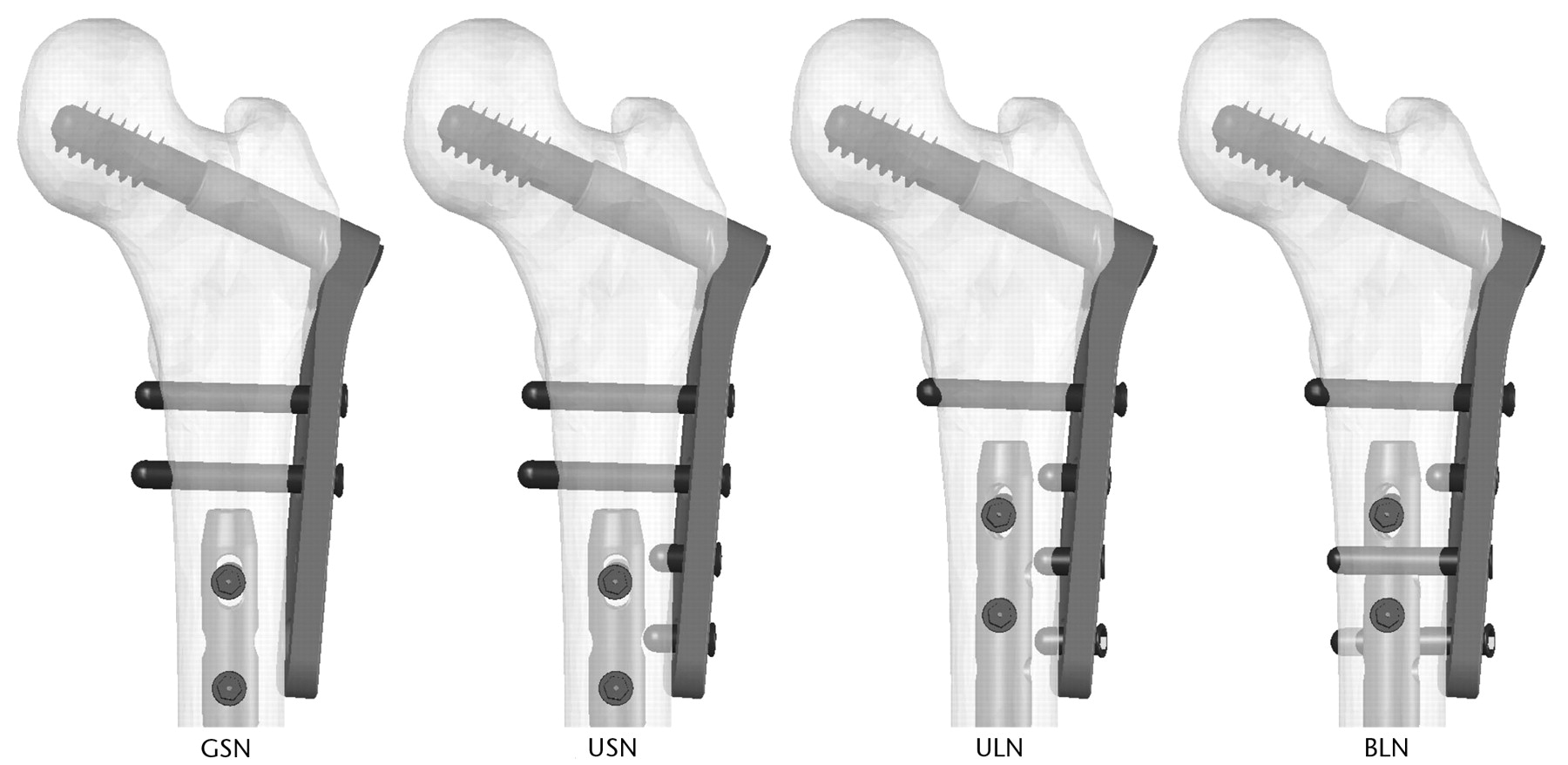
Fig. 1
Diagrams showing the configurations of fixation: gapped short nail (GSN), unicortical short nail (USN), unicortical long nail (ULN), and bicortical long nail (BLN). Only the proximal femur is shown. GSN, USN, and BLN were tested on synthetic femora; ULN and BLN were tested on cadaveric femora.
The next group, ‘unicortical short nail’ (USN, n = 10), was similar to GSN in that it had a 12 mm diameter × 320 mm length retrograde IM nail inserted to overlap the distal two screw holes of the DHS, and bicortical screws were inserted into the two proximal screw holes of the DHS. It differed from GSN in that two unicortical screws were applied to the two distal holes of the DHS side plate, creating a construct that had a bridge between the DHS and IM nail, and thereby eliminating the gap. As with GSN, the IM nail was then locked proximally and distally with two bicortical screws (Fig. 1).
The third group, ‘bicortical long nail’ (BLN, n = 9), incorporated a 12 mm diameter × 340 mm length retrograde IM nail. This was 20 mm longer than the IM nails used in GSN and USN, such that it overlapped the distal three screw holes of the DHS side plate. As with GSN and USN, a bicortical screw was inserted in the most proximal hole of the DHS side plate. Two bicortical screws were inserted at approximately 45° from perpendicular in the two distal holes of the plate, with the most distal screw angled posterior to the IM nail and the other angled anterior to the IM nail. A unicortical screw was then inserted into the remaining open third hole of the side plate (Fig. 1).
Cadaveric model
Ten cadaveric femora were divided into two paired groups in order to determine the effects of implant configuration on biological material and to isolate the effects of screw configurations from nail length. A dual-energy X-ray absorptiometry (DXA) scan was taken of each femoral neck, trochanter, and intertrochanteric regions with a Hologics QDR-4500A (Hologics Inc., Waltham, Massachusetts) to determine bone mineral density. As with the synthetic groups, all femurs used the same DHS (DePuy) with a 130° neck angle, 4-hole side plate, and 95 mm sliding screw. All hardware was implanted according to manufacturer’s instructions.
The BLN cadaveric group was instrumented in a similar manner to the synthetic BLN group, using a 340 mm length IM nail and a DHS side plate with identical screw configuration. It only differed in that the IM nail diameter of 11 mm for the cadaveric tests was smaller than the 12 mm diameter used for the synthetic tests.
A second cadaveric group, ‘unicortical long nail’ (ULN), was constructed using an IM nail identical in diameter and length to the BLN cadaveric group (Fig. 1). Therefore, the IM nail for the ULN cadaveric group was 20 mm longer and 1 mm smaller in diameter than that used in the synthetic USN group. The same DHS and IM screw configuration was used in ULN, as in USN, with the exception of the second most proximal bicortical screw of USN being replaced by a unicortical screw in ULN.
Experimental testing
The distal end of each femur was secured in a 2 inch × 3 inch polyvinyl chloride (PVC) pipe connector by two 1/8 inch transfixing pins drilled through the femoral condyles prior to filling the connector with polymethylmethacrylate. The femurs were then placed in a model 1321 Instron biaxial servohydraulic testing machine (Instron Corp., Canton, Massachusetts) outfitted with a TestStar II system for digital control and data acquisition (MTS Systems, Eden Prairie, Minnesota) by attaching the PVC connector to a custom-made fixture that allowed collinear alignment between the center of the greater trochanter, the distal femur, and the Instron actuator. The femoral head and greater trochanter were placed in a custom metal jig attached to the actuator shaft to allow rotational and axial loads to be applied directly to the femoral shaft. The proximal femur was secured to the jig with wooden shims and a 1/8 inch transfixing pin drilled through the jig and femoral head inferior to the DHS lag screw. An axial load of 22.7 kg (50 pounds) was applied to the specimen, and then the femoral head was internally rotated through a 90° arc over one second to simulate pivoting on a planted foot (Fig. 2).
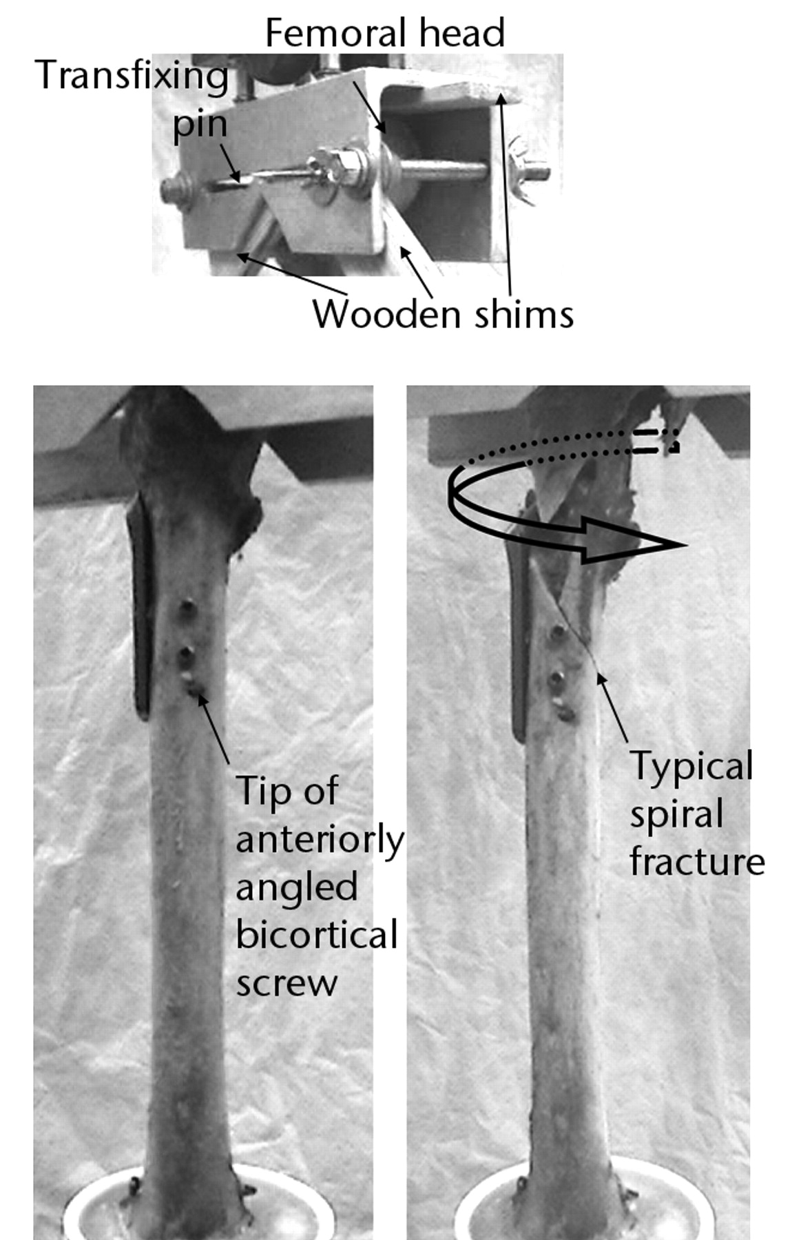
Fig. 2
Photographs of the specimen setup in the Instron testing machine, showing fixation of the specimen to the jig (top), and anterior views of a cadaveric BLN specimen before torsional loading to failure (left) and after failure with fragment rotated back to starting position (right).
A torque (Nm) versus angular rotation (°) curve was generated to determine torsional properties for each synthetic and cadaveric femur. Torque monotonically increased with rotation until sudden fracture for each construct. Torsional stiffness (Nm/°) was defined as the slope of the linear portion from 5 Nm to 25 Nm for synthetic femora and from 5 Nm to 40 Nm for cadaveric femora. Energy to failure (Nm) was determined by integration of the area under each curve from the start of test until the peak torque occurring immediately before a sharp decline. The torque and degrees of rotation corresponding to that peak defined the point of failure.
Statistical analysis
Data from the synthetic femora were analysed via analysis of variance (ANOVA) followed by Tukey-Kramer post-hoc pairwise comparison. Cadaveric data was analysed via paired t-tests. Statistical significance was set at a p-value ≤ 0.05.
Results
The modes of failure were similar for the cadaveric (Fig. 2) and synthetic constructs. The typical fracture pattern was a spiral fracture at the proximal tip of the IM nail, which encompassed either the proximal interlocking screw hole of the IM nail or one of the screw holes of the DHS sideplate. Significant subtrochanteric comminution and extension of the fracture through the DHS lag screw hole were seen in the majority of the non-gapped cases, due to rotation and pullout of the proximal DHS sideplate screws. The fracture pattern in this study replicates the clinical failures noted.
Synthetic model
A trend was apparent for BLN to be the strongest and GSN the weakest, with USN performance falling in between the two. While torsional stiffness did not reveal a significant effect amongst the three constructs (p = 0.49), BLN was significantly higher than GSN in energy to failure (p = 0.04) (Fig. 3). No significant difference in energy to failure was observed between USN and GSN (p = 0.71) or between USN and BLN (p = 0.19). Additionally, BLN had a significantly higher torque at failure than GSN (p = 0.02); but, there was no significant difference in torque at failure between USN and GSN (p = 0.55) nor between USN and BLN (p = 0.15) (Fig. 4). For degrees of rotation at failure, a significant effect was not found among the groups (all p > 0.37).
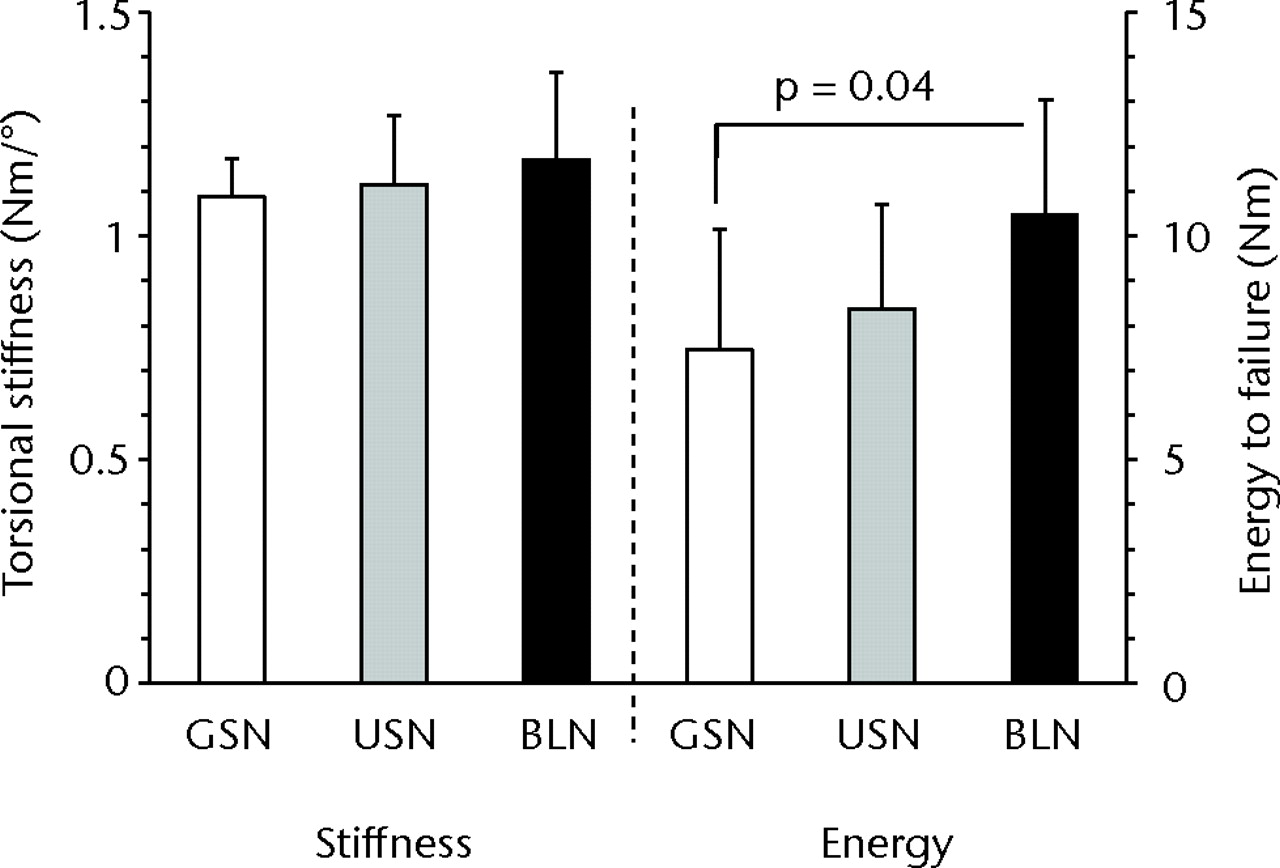
Fig. 3
Bar charts showing torsional stiffness and energy to failure for the three synthetic constructs of gapped short nail (GSN), unicortical short nail (USN) and bicortical long nail (BLN). A statistically significant difference was observed for energy to failure between GSN and BLN (p = 0.04). The error bars depict the standard deviation.
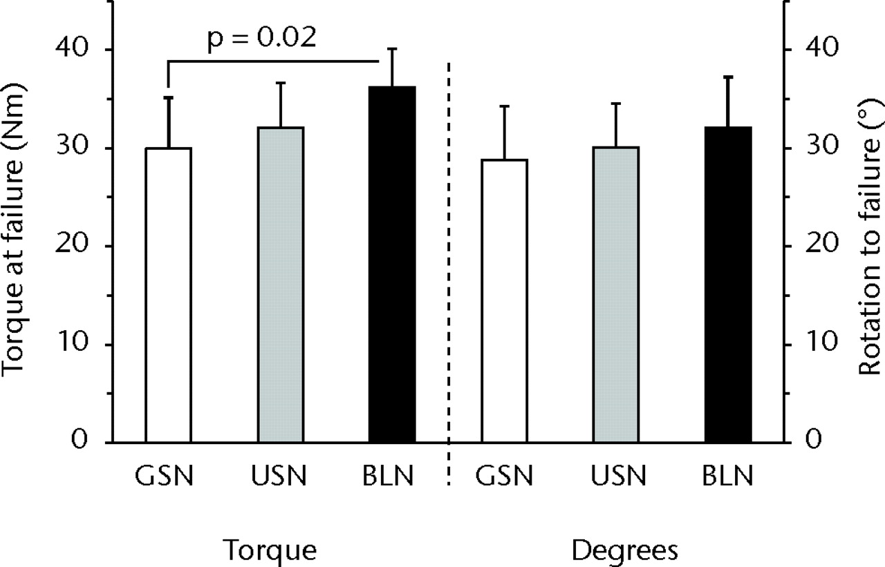
Fig. 4
Bar charts showing torque at failure and degrees of rotation to failure for the three synthetic constructs of gapped short nail (GSN), unicortical short nail (USN) and bicortical long nail (BLN). A statistically significant difference was observed for torque at failure between GSN and BLN (p = 0.02). The error bars depict the standard deviation.
Cadaveric model
The mean bone mineral density for the cadaveric specimens was 0.73 gm/cm2 (0.60 to 0.86) in the greater trochanter, 0.82 gm/cm2 (0.66 to 0.97) in the femoral neck and 1.02 gm/cm2 (0.80 to 1.16) in the intertrochanteric region. No significant difference in bone mineral density was detected between femora tested with ULN versus BLN in the greater trochanter (p = 0.65), femoral neck (p = 0.34) or the intertrochanteric region (p = 0.90). Similar to tests using synthetic femora, BLN tended to be stronger than ULN. However, significant differences were not detected between ULN and BLN for the parameters measured: torsional stiffness (p = 0.62), energy to failure (p = 0.51), torque at failure (p = 0.77), and degrees of rotation at failure (p = 0.62) (Figs 5 and 6). While power was low (< 0.1) for these parameters, the focus of the cadaveric tests was to ensure that trends were comparable to conclusions drawn from synthetic tests, which was achieved.
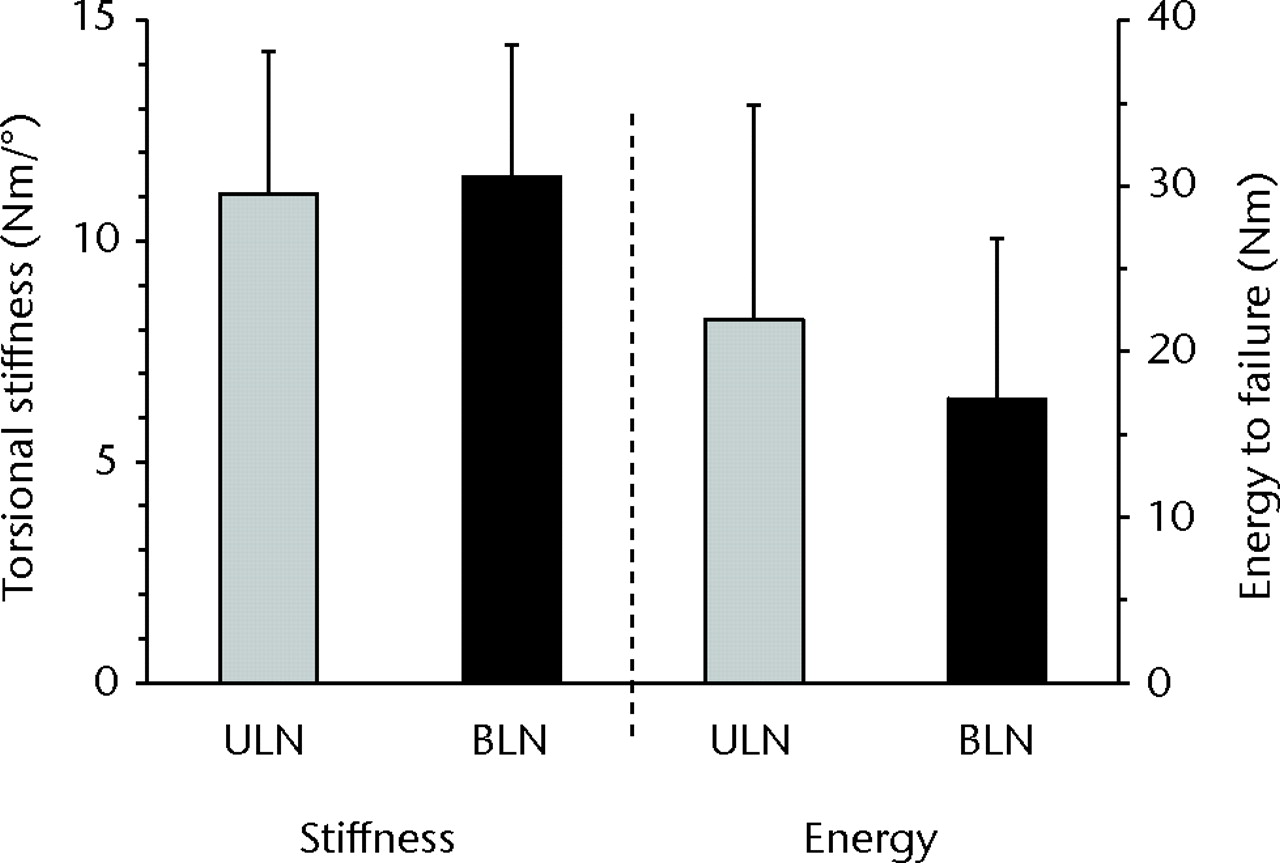
Fig. 5
Bar charts showing torsional stiffness and energy to failure for the two cadaveric constructs of unicortical long nail (ULN) and bicortical long nail (BLN). No statistically significant differences were observed, despite a higher mean energy required for failure in the ULN construct. The error bars depict the standard deviation.
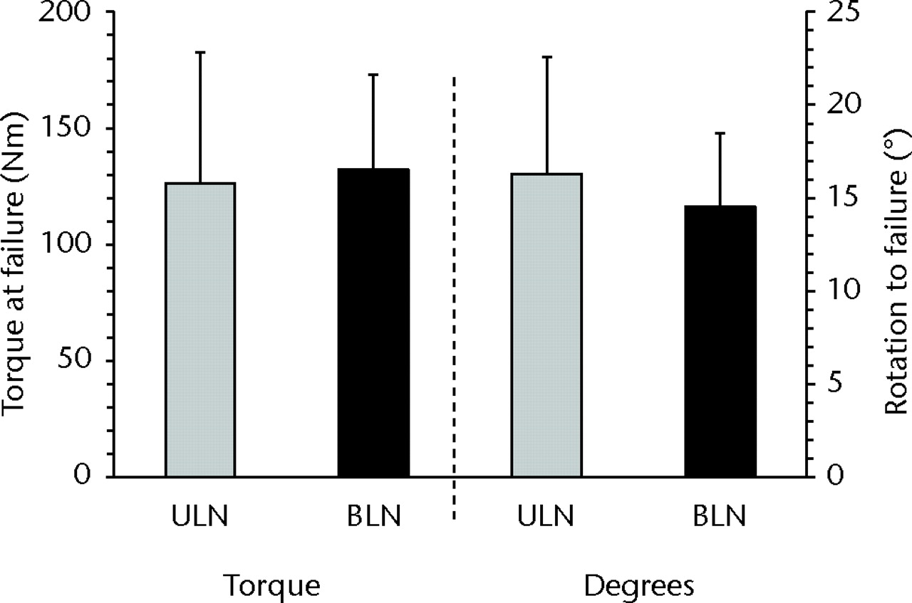
Fig. 6
Bar charts showing torque at failure and degrees of rotation for the two cadaveric constructs of unicortical long nail (ULN) and bicortical long nail (BLN). No statistically significant differences were observed. The error bars depict the standard deviation.
Discussion
At this institution, treatment of concomitant ipsilateral fractures of the femoral neck/trochanter and shaft consists of addressing the fractures as two separate and distinct injuries, with fixation of the shaft with a retrograde IM nail and fixation of the neck or trochanteric fracture with a DHS. This technique has been proven to be as stable and efficacious as alternate two-device constructs8,17 and may have a reduced rate of malreduction versus repair of both fractures with a single construct using either cephallomedullary or reconstructive nails.2,9,18,19 We have observed a non-traumatic fracture in the gapped area of a two implant construct in a patient with ipsilateral intertrochanteric and shaft fractures after the fractures have healed, indicating that a stress riser may exist in this gapped region.
Three different synthetic constructs, termed GSN, USN, and BLN, were proposed as methods of fixation, with the GSN group representing the traditional mechanism in which re-fracture was observed. The BLN construct was theorised to be the strongest construct due to maximal overlap of implants and bicortical fixation of side plate distal screws. The USN construct represented a minimal approach to eliminating the gap present in GSN where USN differed from GSN only in the insertion of unicortical screws in the two distal holes of the DHS side plate, and was anticipated to be intermediate to GSN and BLN in terms of strength. To simulate the loading conditions experienced by our index patient at the time of refracture, a compressive axial load followed by torsion were applied to our biomechanical constructs.
Synthetic femora testing found the torsional properties of GSN to be lowest and BLN to be highest with statistically significant differences in failure torque and energy between GSN and BLN, lending support to our hypothesis. The benefit due solely to bridging the gap with unicortical screws showed trends between USN and GSN. The improved torsional characteristics of BLN are likely due to the combination of two factors: 1) the use of the longer angled screws in the two most distal DHS side plate screw holes allowing for bicortical purchase to the femur; and 2) the implantation of a longer IM nail allowing for increased overlap of the IM nail and DHS side plate.
The results of the synthetic model imply that if one is unable to adequately install the bicortical angled screws during an attempt at BLN, installation of unicortical screws as a fall-back plan may still provide benefit as compared to no screws. With that conclusion, cadaveric testing of ULN and BLN constructs used the same length IM nail simulating the same approach with the only exception being the most distal DHS side plate screws. Thus ULN simulated the fall-back position of a BLN approach that could not be completed as desired but instead had unicortical screws placed in the two most distal DHS side plate screw holes. The results of this testing implied that BLN was slightly stronger than ULN, though no significant difference was detected between the constructs (torsional stiffness, p = 0.62; torque at failure, p = 0.77).
The literature proposes that ‘kissing’ or ‘overlapping’ of implants using a compression hip screw and IM nail construct will increase failure load.13 This result was echoed in our synthetic testing, with the BLN construct having increased strength compared with the GSN and USN constructs. Our modes of failure were also similar to the published results,13 with spiral fractures and comminution resulting from screw cutout occurring generally between the distal bicortical sideplate screw and the proximal IM nail screw. Although the prior study simulated a fall on the greater trochanter as a traumatic event, as opposed to our mode of loading, preset internal rotation of the femoral neck with the position of the femur during loading may have resulted in a rotational force leading to their observed spiral fractures at failure.
Another study compared different fracture fixation techniques for torsional stiffness followed by axial load to failure.8 The DHS and IM nail construct showed comparable results to the other constructs. In axial load to failure, failure modes were screw cutout at the femoral neck/head, intertrochanteric gap widening, and nail bending.8 The spiral fracture pattern between the implants seen by Harris et al13 as well as our own testing was not observed, due to the absence of any torsional force to failure.
Although fixation of the GSN and USN constructs in synthetic and ULN in cadaveric femora was relatively straightforward, challenges in DHS fixation with the BLN group were encountered particularly with placement of the bicortical screws. On several occasions, it proved difficult to find a suitable angle of entry that would both fix the DHS side plate in an adequate position as well as provide suitable bicortical purchase around the IM nail. This difficulty in angulation of screws was also found in the insertion of the proximal screws with cephallomedullary or reconstructive nails that can impair single-construct use10-12 and similarly may impair the use of the BLN construct. The cadaveric results suggest that ULN is a good alternative approach if BLN is not achievable.
This study examined different configurations of DHS and IM nail in both synthetic and cadaveric models. While synthetic bone properties differ from cadaveric bone, tests in synthetic bone can be useful to illustrate differences that would exist between configurations. This then permitted two configurations to be analysed in paired cadaveric specimens. Even with the property differences, the fracture patterns in the synthetic bone were comparable to that of cadaveric testing as well as clinically documented cases.
Limitations of this study include that only one mode of loading was examined. Other biomechanical studies have simulated either a traumatic event as may be experienced by loading on the greater trochanter or failure by axial loading. Our study however applied the combined loading of a small axial load followed by increasing rotation simulating that experienced by our index patient during refracture. Magnitudes of these loads were unknown and had to be estimated.
For the loading scenario simulated, this study supports the use of two different constructs, both using long IM nailing combined with additional screw fixation of the DHS to the femur, to reduce the risk of ipsilateral shaft and neck/trochanteric fractures after union. Modifying the original construct by lengthening the IM nail to provide maximal implant overlap and securing the distal holes of the DHS side plate is implicated as a means to increase construct strength. The BLN construct incorporating both the longer nail and bicortical purchase of the distal side plate was shown to be superior in stabilisation as compared with the GSN construct that had neither of these modifications. However, difficulty in placement of the angled DHS screws in BLN may limit its use to only select patients with suitable anatomy. The ULN construct may also provide a strength advantage, albeit not as great as with the BLN construct, and thus represents an alternative technique that can be used with concomitant fractures.
The authors would like to thank S. Carroll for assistance with the measurement of bone mineral density, and J. Iaquinto, PhD, for provision of the images given in Figure 1.
1 Alho A . Concurrent ipsilateral fractures of the hip and femoral shaft: a meta-analysis of 659 cases. Acta Orthop Scand1996;67:19–28.CrossrefPubMed Google Scholar
2 Watson JT , MoedBR. Ipsilateral femoral neck and shaft fractures: complications and their treatment. Clin Orthop Relat Res2002;399:78–86.CrossrefPubMed Google Scholar
3 Cannada LK , VieheT, CatesCA, et al.A retrospective review of high-energy femoral neck-shaft fractures. J Orthop Trauma2009;23:254–260.CrossrefPubMed Google Scholar
4 Tsai CH , HsuHC, FongYC, et al.Treatment for ipsilateral fractures of femoral neck and shaft. Injury2009;40:778–782.CrossrefPubMed Google Scholar
5 Alho A . Ipsilateral femoral neck and shaft fractures. J Am Acad Orthop Surg1999;7:76–78.CrossrefPubMed Google Scholar
6 Friedman RJ , WymanET Jr. Ipsilateral hip and femoral shaft fractures. Clin Orthop Relat Res1986;208:188–194.CrossrefPubMed Google Scholar
7 Peljovich AE , PattersonBM. Ipsilateral femoral neck and shaft fractures. J Am Acad Orthop Surg1998;6:106–113.CrossrefPubMed Google Scholar
8 McConnell A , ZderoR, SyedK, PeskunC, SchemitschE. The biomechanics of ipsilateral intertrochanteric and femoral shaft fractures: a comparison of 5 fracture fixation techniques. J Orthop Trauma2008;22:517–524.CrossrefPubMed Google Scholar
9 Bedi A , KarunakarMA, CaronT, SandersRW, HaidukewychGJ. Accuracy of reduction of ipsilateral femoral neck and shaft fractures: an analysis of various internal fixation strategies. J Orthop Trauma2009;23:249–253. Google Scholar
10 Jain P , MainiL, MishraP, UpadhyayA, AgarwalA. Cephalomedullary interlocked nail for ipsilateral hip and femoral shaft fractures. Injury2004;35:1031–1038.CrossrefPubMed Google Scholar
11 Abalo A , DossimA, Ouro BangnaAF, et al.Dynamic hip screw and compression plate fixation of ipsilateral femoral neck and shaft fractures. J Orthop Surg (Hong Kong)2008;16:35–38.CrossrefPubMed Google Scholar
12 Singh R , RohillaR, MaguNK, et al.Ipsilateral femoral neck and shaft fractures: a retrospective analysis of two treatment methods. J Orthop Traumatol2008;9:141–147.CrossrefPubMed Google Scholar
13 Harris T , RuthJT, SzivekJ, HaywoodB. The effect on implant overlap on the mechanical properties of the femur. J Trauma2003;54:930–935. Google Scholar
14 Mounasamy V, Sathpathy J, Willis MC. Stress fractures in the gapped area of a two implant construct: a case report. Eur J Orthop Surg Traumatol 2011:Epub. Google Scholar
15 Peskun C , McKeeM, KrederH, et al.Functional outcome of ipsilateral intertrochanteric and femoral shaft fractures. J Orthop Trauma2008;22:102–106.CrossrefPubMed Google Scholar
16 Leibner ED , MosheiffR, SafranO, Abu-SnienehK, LiebergallM. Femoral fracture at the proximal end of an intramedullary supracondylar nail: a case report. Am J Orthop1999;28:53–55.PubMed Google Scholar
17 Oh CW , OhJK, ParkBC, et al.Retrograde nailing with subsequent screw fixation for ipsilateral femoral shaft and neck fractures. Arch Orthop Trauma Surg2006;126:448–453.CrossrefPubMed Google Scholar
18 Bhandari M . Ipsilateral femoral neck and shaft fractures. J Orthop Trauma2003;17:138–140.CrossrefPubMed Google Scholar
19 Wiss DA , SimaW, BrienWW. Ipsilateral fractures of the femoral neck and shaft. J Orthop Trauma1992;6:159–166.PubMed Google Scholar
Funding statement:
The donation of hardware by DePuy Orthopaedics, Inc., and the partial financial support from the Richmond Eye & Ear Healthcare Alliance Research and Education Fund, is greatly appreciated. These organisations played no role in the design of this study or in the collection, analysis and interpretation of data.
Author contributions:
B. J. Swinteck: Study design, Data collection, Data analysis, Interpretation of results, Writing the paper
D. L. Phan: Data collection, Data analysis, Writing the paper
J. Jani: Data collection, Data analysis, Writing the paper
V. Mounasamy: Study design, Interpretation of results, Writing the paper
J. R. Owen: Study design, Data collection, Data analysis, Writing the paper
J. S. Wayne: Study design, Data collection, Data analysis, Interpretation of results, Writing the paper
ICMJE Conflict of Interest:
None declared
©2012 British Editorial Society of Bone and Joint Surgery. This is an open-access article distributed under the terms of the Creative Commons Attributions licence, which permits unrestricted use, distribution, and reproduction in any medium, but not for commercial gain, provided the original author and source are credited.
