


Abstract
Objectives
Metal-on-metal (MoM) hip resurfacing was introduced into clinical practice because it was perceived to be a better alternative to conventional total hip replacement for young and active patients. However, an increasing number of reports of complications have arisen focusing on design and orientation of the components, the generation of metallic wear particles and serum levels of metallic ions. The procedure introduced a combination of two elements: large-dimension components and hard abrasive particles of metal wear. The objective of our study was to investigate the theory that microseparation of the articular surfaces draws in a high volume of bursal fluid and its contents into the articulation, and at relocation under load would generate high pressures of fluid ejection, resulting in an abrasive water jet.
Methods
This theoretical concept using MoM resurfacing components (head diameter 55 mm) was modelled mathematically and confirmed experimentally using a material-testing machine that pushed the head into the cup at a rate of 1000 mm/min until fully engaged.
Results
The mathematical model showed the pattern but not the force of fluid ejection, the highest pressures were expected when the separation of the components was only a fraction of one millimetre. The experimental work confirmed the results; with the mean peak ejection pressure of 43 763 N/m2 equivalent to 306 mmHg or 5 psi.
Conclusions
The mechanical effect of the high-pressure abrasive water jet is the likely cause of the spectrum of complications reported with metal-on-metal resurfacing. Investigating serum levels of metallic elements may not be the best method for assessing the local mechanical effects of the abrasive water jet.
Article focus
Large metal-on-metal (MoM) resurfacing components
Microseparation of components
Abrasive high-pressure fluid jet
Key messages
The large dimensions of MoM resurfacing components and fluid containing abrasive wear particles are drawn in to articulation during the separation phase
The fluid and its abrasive contents are forced out of the articulation at high pressure on relocation
Relocation after microseparation generates a high pressure abrasive fluid jet
Strengths and limitations
Experimental results confirm the theoretical concept and mathematical model
Abrasive water jet explains the spectrum of complications reported
Only one size of components used in the experimental model
Introduction
Modern metal-on-metal (MoM) hip resurfacing was introduced as an theoretically less invasive procedure, as it was considered that the results of conventional total hip replacement (THR) in young patients with osteoarthritis had not been encouraging, even with improvements in the technique of fixation and bearing surfaces.1 It was also claimed that the presence of a normal-sized femoral head in its normal location lowered the risk of dislocation, allowing the patient to regain a full range of movement and a more physiological loading of the proximal femur.1 With time, and an increasing number of MoM arthroplasties of the hip being performed, reports of complications surfaced, including narrowing2 and fracture3 of the femoral neck, ischaemic muscle necrosis,4,5 nerve involvement6 and pseudotumours.6 Pseudotumours were considered to be the toxic effects of the large amount of metallic debris,6 arising from malposition of the acetabular component with higher risks of impingement and edge loading.7,8 The desirable parameters for orientation of the acetabular component have been defined,7 but the optimal geometry of the component has not been defined.
Detailed histological studies have concluded that the changes were due to lymphocyte-mediated immuno-logical response.9,10
In an attempt to justify its use, it has been suggested that MoM hip resurfacing is a means of delaying THR; its use in clinical practice was justified by the “need for innovative solutions in young arthroplasty patients”.1 Whether the operation is defined as a replacement, arthroplasty, reconstruction or even resurfacing is a matter of semantics; the importance lies in the mechanical characteristics and the function of the implant in vivo.
We suggest that many aspects of this type of surgery are better understood when considered for what the implant truly is: a neuropathic spacer functioning within a foreign body bursa. The initial fundamental problem is mechanical: separation and relocation of the articulating surfaces. This aspect has been well documented in the context of post-operative subluxation, dislocation and revision for dislocation.12-14 More recently the term “microseparation” has been introduced.15This has been reported in 23.1% of cases and was considered to be a result of muscle weakness, impingement, malposition of the acetabular component or a short offset stem.16 We agree with Ryou et al16 that separation of the articular surfaces at some stages of activity may in fact be a feature of all designs of total hip arthroplasty. MoM hip resurfacing, however, has introduced a combination of two new elements: large components and hard, abrasive metallic wear particles.
Using mathematical modelling and experimental evaluation, the aim of our study was to investigate the mechanical consequences of the sequence of separation and relocation of the articular surfaces in MoM arthroplasty of the hip, and in particular the ejection pressures generated when the components relocate. The biological effects of the metallic debris on the soft tissues are outside the scope of this study.
Materials and Methods
Mathematical modelling
A mathematical model was first undertaken, in order to create hypotheses to be investigated during experimental evaluation. For each increment of circumferential separation between the acetabular and femoral components, four parameters were calculated:
1) The circumferential area of separation between the two components, calculated by subtracting the area of the femoral component from the area of the acetabular component at each particular stage of relocation (Table I).
2) The linear separation distance between the summit of the femoral component and the centre of the acetabular component, calculated using Pythagoras’ Theorem: r12 = r22 + d2, as shown in Table I and Figure 1.
Table I
Linear separation between the femoral and acetabular components at various circumferential separation distances
| Circumferential separation (mm) | Socket radius (mm) | Femoral head radius (mm) | Linear separation (d) between socket and femoral head (mm) |
|---|---|---|---|
| 0 | 27.5 | 27.5 | 0.00 |
| 0.1 | 27.5 | 27.4 | 2.34 |
| 0.2 | 27.5 | 27.3 | 3.31 |
| 0.3 | 27.5 | 27.2 | 4.05 |
| 0.4 | 27.5 | 27.1 | 4.67 |
| 0.5 | 27.5 | 27.0 | 5.22 |
| 0.6 | 27.5 | 26.9 | 5.71 |
| 0.7 | 27.5 | 26.8 | 6.17 |
| 0.8 | 27.5 | 26.7 | 6.58 |
| 0.9 | 27.5 | 26.6 | 6.98 |
| 1.0 | 27.5 | 26.5 | 7.35 |

Fig. 1
Cross-sectional diagram of a metal-on-metal hip resurfacing (diameter 55 mm) showing how the linear separation between the femoral and acetabular -components (d) was calculated at various circumferential separation distances.
3) The volume of the space between the two components, calculated by subtracting the volume of the part of the femoral head sitting in the acetabular component from the volume of the hemispherical component using the formula: [(2/3 × πr13) – (2/3 × πr22)(r1 – d)], as shown in Table II and Figure 2.
Table II
Volume of the space between the femoral and acetabular components at a linear separation of d
| Linear separation (d) between socket and femoral head (mm) | Volume of socket (mm3) | Volume of -hemisphere (mm3) | Volume of space between socket and femoral head (mm3) |
|---|---|---|---|
| 0.00 | 43 556.87 | 43 556.87 | 0.00 |
| 2.34 | 43 556.87 | 39 556.45 | 4000.42 |
| 3.31 | 43 556.87 | 37 758.02 | 5798.85 |
| 4.05 | 43 556.87 | 36 334.75 | 7222.12 |
| 4.67 | 43 556.87 | 35 110.72 | 8446.15 |
| 5.22 | 43 556.87 | 34 017.18 | 9539.69 |
| 5.71 | 43 556.87 | 33 018.53 | 10 538.34 |
| 6.17 | 43 556.87 | 32 093.44 | 11 463.43 |
| 6.58 | 43 556.87 | 31 227.88 | 12 328.99 |
| 6.98 | 43 556.87 | 30 412.02 | 13 144.85 |
| 7.35 | 43 556.87 | 29 638.65 | 13 918.22 |
Fig. 2
Cross-sectional diagram of a metal-on-metal hip resurfacing (diameter 55 mm) showing how the volume of the space between the femoral and acetabular components was calculated for a linear separation of d.
4) The potential height of fluid column ejected, calculated by dividing the volume of the space between the components by the circumferential separation area between the components – at the particular stage of relocation. This is shown in Table III and Figure 3.
Table III
Height of the fluid column generated at a linear separation of d
| Linear separation (d) between socket and femoral head (mm) | Volume of space between socket and femoral head (mm3) | Circumferential separation area (mm2) | Height of column (mm) |
|---|---|---|---|
| 0.00 | 0.00 | 0.0 | 231.9 |
| 2.34 | 4000.42 | 17.2 | 231.9 |
| 3.31 | 5798.85 | 34.4 | 168.4 |
| 4.05 | 7222.12 | 51.6 | 140.1 |
| 4.67 | 8446.15 | 68.6 | 123.1 |
| 5.22 | 9539.69 | 85.6 | 111.4 |
| 5.71 | 10 538.34 | 102.5 | 102.8 |
| 6.17 | 11 463.43 | 119.4 | 96.0 |
| 6.58 | 12 328.99 | 136.2 | 90.5 |
| 6.98 | 13 144.85 | 153.0 | 85.9 |
| 7.35 | 13 918.22 | 169.6 | 82.0 |
Fig. 3
Graph showing the relationship between the separation distance of the components and the height of the fluid column, as assessed using the mathematical model.
The mathematical model showed the pattern but not the force of fluid ejection. The highest expected pressures would occur at the very end stage of component relocation when the separation of the components would be only a fraction of 1 mm. Hence the term “micro-separation” is justified in this context.
Experimental evaluation
We used MoM resurfacing components (DePuy International, Leeds, United Kingdom) with a head radius of 27.5 mm (Fig. 4). These were assembled in a specially designed cell (Fig. 5). The acetabular component was mounted horizontally and secured with acrylic cement. The metal head was mounted on a metallic taper, concentrically, above the acetabular component, which was filled with water and covered with a silicone membrane in order to simulate the capsule of the hip joint. The assembled cell was placed centrally in a material testing machine (Instron, High Wycombe, United Kingdom) with a separation gap of 3.5 mm between the head and the acetabular component (the gap dictated by the set-up of the experiment). The mechanism was programmed using Bluehill 2 software (Instron) to push the head into the cup at 1000 mm/min, the maximum speed possible, until fully engaged. A load cell of 5 kN was used to measure the load at a rate of 100 Hz, as the head became fully engaged.

Figs. 4a - 4b
Three-dimensional image (a) and cross-sectional diagram (b) of a metal-on-metal hip resurfacing (55 mm diameter) with both the femoral and acetabular components in full contact (r1, radius of the femoral head).
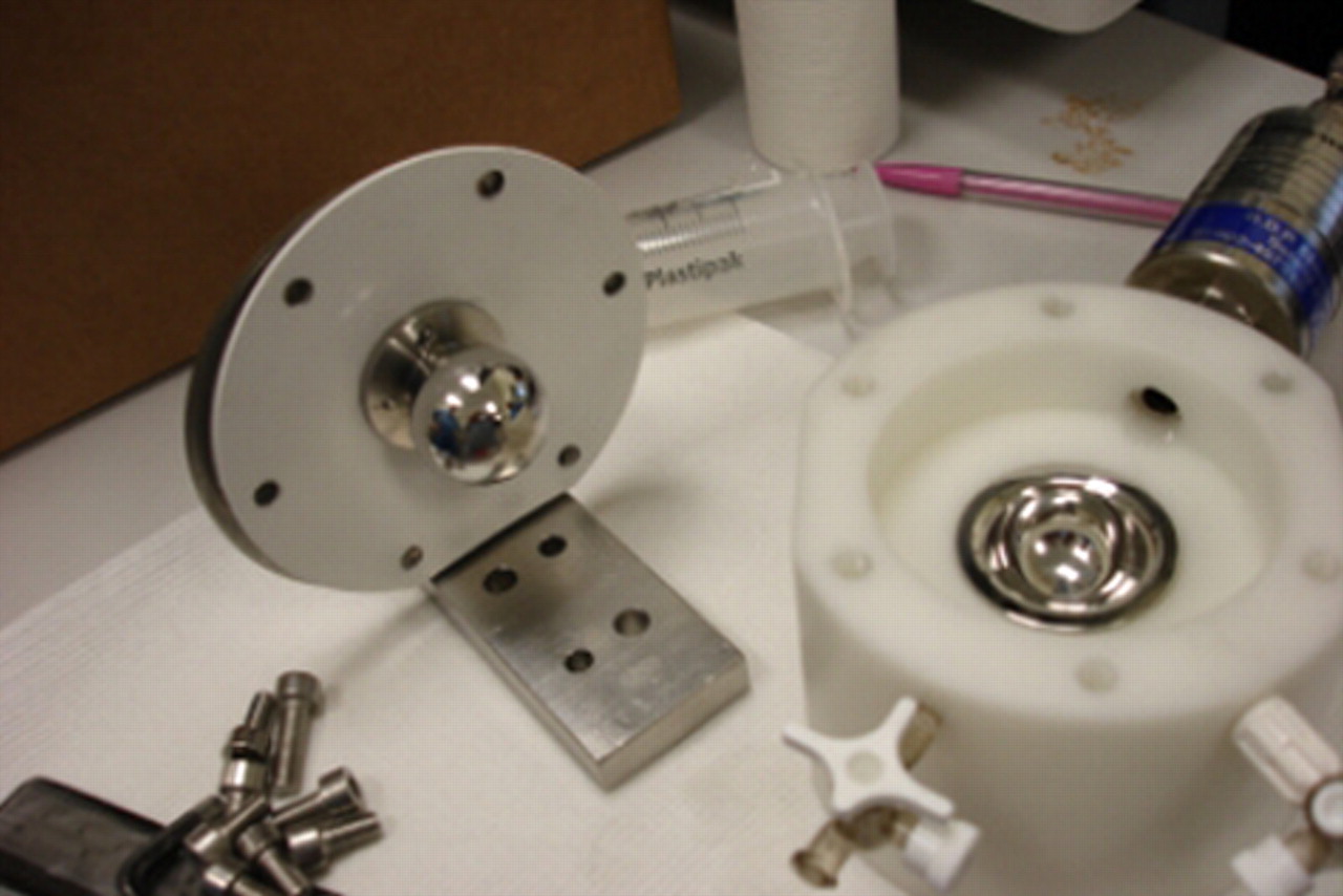
Figs. 5a - 5b
Photographs of the mechanical testing, showing a) the external view, with the resurfacing components assembled in a specially designed cell with the acetabular component mounted horizontally and secured with acrylic cement and the head mounted on a metallic taper, concentrically, above the cup, and b) the internal view: the cup was filled with water and covered with a silicone membrane in order to simulate the capsule of the hip.
A pressure transducer (Honeywell-Sensotec; Honeywell International Inc., Columbus, Ohio) connected to a calibrated transducer indicator (RDP Electronics Ltd, Wolverhampton, United Kingdom) was used to record peak pressures of the fluid (in N/m2 and mmHg) within the chamber on full relocation of the head within the acetabular component.
A data acquisition card (DAQ; National Instrument Corporation (UK) Ltd, Newbury, United Kingdom) was used to record pressure throughout the experiment. The DAQ was connected to the transducer indicator from one side and to the laptop from the other side. Lab.view 8.8 software (National Instrument Corporation (UK) Ltd) was used to record the voltage output during the experiment at a rate of 1000 Hz. This was calibrated against a transducer indicator (RDP Electronics Ltd) to obtain a conversion equation to convert the output voltage into output pressure and recorded graphically as time (seconds) and pressure (N/m2). Five recordings were made.
Results
The experiments confirmed the patterns of pressure that had been predicted mathematically. The mean time from contact to full relocation of the head within the cup was 0.17 seconds (0.14 to 0.23). The mean peak load on the head at full relocation was 101.36 N (98.87 to 103.58). The mean peak ejection pressure of the fluid within the chamber at full relocation was 43 763 N/m2 (41 198 to 46 504) (Fig. 6), equivalent to a mean of 5 psi or 306 mmHg (288 to 325), which ismore than twice the accepted normal systolic blood pressure.
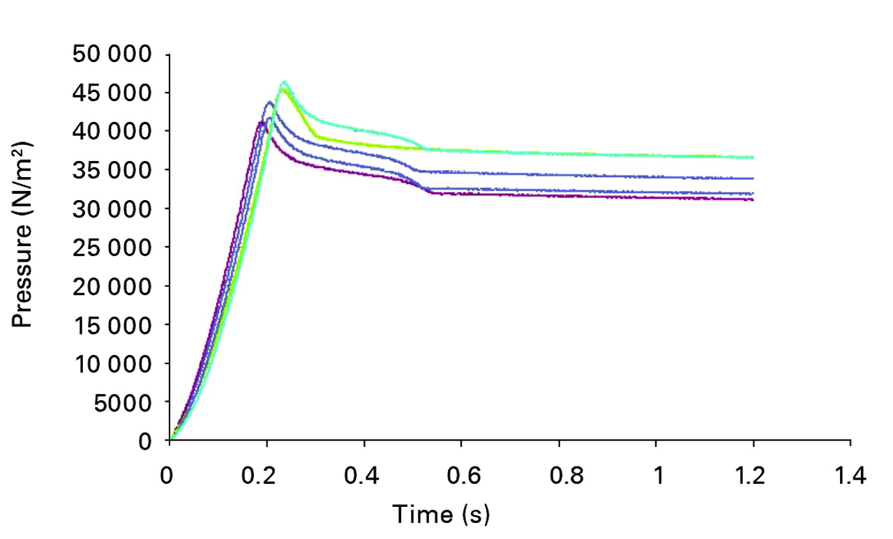
Fig. 6
Graph showing the results of five experiments showing the ejection pressure of the fluid within the chamber during the relocation. The mean peak ejection pressure of the fluid within the chamber at full relocation was 43 763 N/m2.
Discussion
Separation of the articulating surfaces is most likely to occur during the swing phase of the walking cycle,16 or at any non-load bearing position, allowing ingress of the bursal fluid and its contents. On relocation, as at the heel strikes, contents would be ejected at high pressure: 43 763 N/m2 as found in our study, equivalent to 5 psi or 306 mmHg, more than twice the normal systolic blood pressure.
The combination of the high ejection pressure of the bursal fluid and the abrasive nature of the metallic wear particles forms a very powerful abrasive water jet17with a damaging effect on the surrounding living tissues. If a level of activity is considered to be approximately 1.5 million load cycles per year,18 then the mechanical consequences can be expected to be a spectrum depending on the frequency and pressure of the abrasive water jets, the tissue affected and their capacity to respond. This could result in the erosion of bone, as reported in the context of narrowing of the femoral neck,2 inflammatory changes,7 ischaemia and even necrosis4,5or pressure effects as reported with recoverable nerve involvement.6 The higher incidence of complications reported in female patients could be explained by higher frequency of the ejection episodes due to the shorter stride to cover the equivalent distance.6,7In our study the position of the components was dictated by the equipment, but the position of the components as achieved at surgery will be a factor in the direction of the abrasive jet and the tissues therefore affected. The ejection pressures would also be expected to be higher when body load and activity level is taken into account. Non-concentric separation/relocation of the components would also account for the rim/stripe wear.7,8,19,20
It will be noted, both from the mathematical model and the experiments, that the highest ejection pressures are generated at the very final stages of component relocation. This has significant clinical implications. The separation of the components need only be minimal, a millimetre or less, for generation of the highest ejection pressures. In this context microseparation16 may in fact be the correct term. The levels of ejection pressure are dependent on the elasticity of the cell housing the implant. Under clinical conditions the bursa housing the implant would be more elastic, reducing the peak pressures, but at the expense of damage to the living tissues and expansion of the cavity.
In terms of the need for innovative solutions in young arthroplasty patients,11 innovations and improvements are more likely to be of benefit when based on the study of long-term results and examination of explanted components. We must distinguish between short-term clinical success of the operation for an individual patient1 and a long-term success of the method of this type of operation.21 Long-term results are results in young patients. Those achieving follow-up of between 30 and 40 years are on average 43 years of age at surgery.21 Therefore increasing follow-up identifies ever younger patients that have undergone the operation.
In summary, MoM articulation demands lubrication. Any lubricant carries abrasive metal particles generated at the level of the articulation, which together form a powerful water jet. Investigating serum metallic ion levels is not the best method to study the damage to tissue as a result of repetitive abrasive water jets; it may be more appropriate to search for systemic evidence of tissue destruction. The complications are best avoided by the cessation of generation of the abrasive metallic wear particles. Any hard-on-hard articulation that generates abrasive wear particles may be expected to present -similar problems.
The authors would like to thank Professor J. Fisher, Professor Z. Jin and the staff of the Institute of Medical and Biological Engineering, University of Leeds, for their help with this study.
1 Daniel J , PynsentPB, McMinnDJ. Metal-on-metal resurfacing of the hip in patients under the age of 55 years with osteoarthritis. J Bone Joint Surg [Br]2004;86-B:177–184.CrossrefPubMed Google Scholar
2 Hing CB , YoungDA, DalzielRE, et al.Narrowing of the neck in resurfacing arthroplasty of the hip: a radiological study. J Bone Joint Surg [Br]2007;89-B:1019–1024.CrossrefPubMed Google Scholar
3 Shimmin AJ , BackD. Femoral neck fractures following Birmingham hip resurfacing: a national review of 50 cases. J Bone Joint Surg [Br]2005;87-B:463–464.CrossrefPubMed Google Scholar
4 Boardman DR , MiddletonFR, KavanaghTG. A benign psoas mass following metal-on-metal resurfacing of the hip. J Bone Joint Surg [Br]2006;88-B:402–404.CrossrefPubMed Google Scholar
5 Ollivere B , DarrahC, BarkerT, NolanJ, PorteousMJ. Early clinical failure of the Birmingham metal-on-metal hip resurfacing is associated with metallosis and soft-tissue necrosis. J Bone Joint Surg [Br]2009;91-B:1025–1030.CrossrefPubMed Google Scholar
6 Pandit H , Glyn-JonesS, McLardy-SmithP, et al.Pseudotumours associated with metal-on-metal hip resurfacings. J Bone Joint Surg [Br]2008;90-B:847–851.CrossrefPubMed Google Scholar
7 De Haan R , CampbellPA, SuEP, De SmetKA. Revision of metal-on-metal resurfacing arthroplasty of the hip: the influence of malpositioning of the components. J Bone Joint Surg [Br]2008;90-B:1158–1163.CrossrefPubMed Google Scholar
8 Hart AJ , BuddhdevP, WinshipP, et al.Cup inclination angle of greater than 50 degrees increases whole blood concentrations of cobalt and chromium ions after metal-on-metal hip resurfacing. Hip Int2008;18:212–219.CrossrefPubMed Google Scholar
9 Willert HG , BuchhornGH, FayyaziA, et al.Metal-on-metal bearings and hypersensitivity in patients with artificial hip joints: a clinical and histomorphological study. J Bone Joint Surg [Am]2005;87-A:28–36. Google Scholar
10 Davies AP , WillertHG, CampbellPA, LearmonthID, CaseCP. An unusual lymphocytic perivascular infiltration in tissues around contemporary metal-on-metal joint replacements. J Bone Joint Surg [Am]2005;87-A:18–27.CrossrefPubMed Google Scholar
11 Simpson JM , VillarRN. Resurfacing registers concern. J Bone Joint Surg [Br]2010;92-B:1493–1497.CrossrefPubMed Google Scholar
12 Berry DJ , von KnochM, SchleckCD, HarmsenWS. Effect of femoral head diameter and operative approach on risk of dislocation after primary total hip arthroplasty. J Bone Joint Surg [Am]2005;87-A:2456–2463.CrossrefPubMed Google Scholar
13 McConway J , O'BrienS, DoranE, ArchboldP, BeverlandD. The use of a posterior lip augmentation device for a revision of recurrent dislocation after primary cemented Charnley/Charnley Elite total hip replacement: results at a mean follow-up of six years and nine months. J Bone Joint Surg [Br]2007;89-B:1581–1585.CrossrefPubMed Google Scholar
14 Wroblewski BM , SineyPD, FlemingPA. The angle-bore acetabular component and dislocation after revision of a failed total hip replacement. J Bone Joint Surg [Br]2006;88-B:184–187.CrossrefPubMed Google Scholar
15 Nevelos J , InghamE, DoyleC, et al.Microseparation of the centers of alumina-alumina artificial hip joints during simulator testing produces clinically relevant wear rates and patterns. J Arthroplasty2000;15:793–795.CrossrefPubMed Google Scholar
16 Ryou S , OhashiH, KadoyaK, et al.Hip position related microseparation after alumina-on-alumina THA. J Bone Joint Surg [Br]2004;86-B(Suppl 3):361. Google Scholar
17 Hashish M . A model of abrasive water jet machining. J Eng Mater Tech1989;3:154–162. Google Scholar
18 Goldsmith AA , DowsonD, WroblewskiBM, et al.Comparative study of the activity of total hip arthroplasty patients and normal subjects. J Arthroplasty2001;16:613–619.CrossrefPubMed Google Scholar
19 Williams S , ButterfieldM, StewartT, et al.Wear and deformation of ceramic-on-polyethylene total hip replacements with joint laxity and swing phase microseparation. Proc Inst Mech Eng H2003;217:147–153.CrossrefPubMed Google Scholar
20 Stewart T , TipperJ, StreicherR, InghamE, FisherJ. Long-term wear of HIPed alumina on alumina bearings for THR under microseparation conditions. J Mater Sci Mater Med2001;12:1053–1056.CrossrefPubMed Google Scholar
21 Wroblewski BM , SineyPD, FlemingPA. Charnley low-frictional torque arthroplasty: follow-up for 30 to 40 years. J Bone Joint Surg [Br]2009;91-B:447–450.CrossrefPubMed Google Scholar
Funding statement:
None declared
Author contributions:
B. M. Wroblewski: Writing the paper, Data analysis, Theoretical/Mathematical/Experimental modelling
P. D. Siney: Theoretical/Mathematical modelling, Data analysis
P. A. Fleming: Data collation, Typing manuscript
ICMJE Conflict of Interest:
None declared
©2012 British Editorial Society of Bone and Joint Surgery. This is an open-access article distributed under the terms of the Creative Commons Attributions licence, which permits unrestricted use, distribution, and reproduction in any medium, but not for commercial gain, provided the original author and source are credited.
