


Abstract
Objectives
Numerous complications following total knee replacement (TKR) relate to the patellofemoral (PF) joint, including pain and patellar maltracking, yet the options for in vivo imaging of the PF joint are limited, especially after TKR. We propose a novel sequential biplane radiological method that permits accurate tracking of the PF and tibiofemoral (TF) joints throughout the range of movement under weightbearing, and test it in knees pre- and post-arthroplasty.
Methods
A total of three knees with end-stage osteoarthritis and three knees that had undergone TKR at more than one year’s follow-up were investigated. In each knee, sequential biplane radiological images were acquired from the sagittal direction (i.e. horizontal X-ray source and 10° below horizontal) for a sequence of eight flexion angles. Three-dimensional implant or bone models were matched to the biplane images to compute the six degrees of freedom of PF tracking and TF kinematics, and other clinical measures.
Results
The mean and standard deviation for the six degrees of freedom of PF tracking and TF kinematics were computed. TF and PF kinematics were highly accurate (< 0.9 mm, < 0.6°) and repeatable.
Conclusions
The developed method permitted measuring of in vivo PF tracking and TF kinematics before and after TKR throughout the range of movement. This method could be a useful tool for investigating differences between cohorts of patients (e.g., with and without pain) impacting clinical decision-making regarding surgical technique, revision surgery or implant design.
Article focus
The purpose was to develop and validate a novel in vivo sequential biplane radiological method that permits accurate tracking of the patellofemoral (PF) and tibiofemoral (TF) joints, throughout the range of movement under weightbearing, before and after total knee replacement (TKR)
Key messages
The developed approach was validated, accurate (0.9 mm, 0.6°) and repeatable
Strengths and limitations
The main strength of this method is that it provides a solution to measure PF joint tracking after TKR. Other advantages include the use of only one X-ray source, increased depth information for greater three-dimensional accuracy, use of the same protocol for pre- and post-TKR subjects, and feasibility for most clinical settings
The biplane acquisitions are sequential, which may result in negligible subject movement
Introduction
Total knee replacement (TKR) is considered a successful surgery based on the rate of revision; however, approximately 18% of patients are not satisfied with the outcome.1 One cause is abnormal kinematics after surgery.2 Several studies have shown significant differences in tibiofemoral (TF) kinematics after surgery3 or in sagittal-plane patellofemoral (PF) tracking.4,5 However, these studies were not able to compare the six degrees of freedom (DOF) of patellofemoral (PF) kinematics after TKR, because the patella is masked by the femoral prosthesis from most directions. Furthermore the polyethylene patellar prosthesis is more difficult to detect than the metal femoral and tibial prostheses.
Previously, in vivo PF motion has been detected through several methods, each with specific limitations. A tracked patellar clamp can only be used for the first 20° of flexion6; an ultrasonic probe is primarily intended to measure mediolateral tracking7; and sagittal fluoroscopy8,9 has poor accuracy in the out-of-plane DOF (mediolateral shift and tilt),10 which are the most clinically relevant.11 Conventional biplane systems have been used to study the natural knee,12,13 but are not easily accessible due to their increased costs, thus making them more of a rarity than the norm. Additionally, the positioning of two X-ray sources and detectors may be a geometric challenge, as the patellar prosthesis is obscured by the femoral prosthesis when viewed from an angle of more than approximately 20° off-sagittal.14 In a recent study, a multi-planar radiological method was introduced to acquire multiple calibrated radiological views of the subject without the geometric limitations of a fixed bi-planar system.14 This method, however, might not be easily adopted for imaging systems with a non-rotary gantry, and requires the use of a motion tracking system. Intra-operative navigation systems can only measure passive kinematics,15,16 and MRI is not only affected by metal artifact distortions,17 but is typically non-weightbearing18 with limited range of movement.19 Therefore, an in vivo technique to obtain the six DOF of weightbearing PF tracking and TF kinematics after TKR throughout the range of movement is needed.
Such a method will allow investigation of clinical questions such as: kinematic differences between patients with and without pain, particularly anterior knee pain; differences in PF tracking of patients with various implant designs; and kinematic changes between the pre- and post-operative joint, all of which can affect satisfaction.20
We propose a novel in vivo radiological protocol to address this need. Some of the important protocol design criteria were the adaptability for routine clinical use, a similar procedure for pre- and post-operative subjects, and measurement of patellar shift and tilt relative to the femoral groove, which can indicate abnormal kinematics.11
The purpose of the present study was to develop and validate an in vivo radiological imaging protocol to measure pre- and post-TKR PF tracking and TF kinematics, as well as the patellar location within the femoral groove. This imaging protocol is expected to provide a robust tool to answer numerous clinical questions related to the PF joint after TKR.
Materials and Methods
The overall procedure consists of the following: acquiring multiple two-dimensional (2D) views throughout the range of movement of the knee; calibrating the images; acquiring three-dimensional (3D) knee information; and performing 2D-3D matching in order to determine the PF tracking and TF kinematics throughout the range of movement. Validation was performed using a prosthesis-implanted artificial bone model. Our institutional review board approved the in vivo subject imaging. Informed consent was obtained from all subjects.
A total of six female subjects were tested: three (aged 55, 59 and 65 years) who were diagnosed with end-stage osteoarthritis and scheduled for TKR surgery (pre-operative knees), and three (aged 59, 65 and 70 years) with TKR in the right knee at more than one year’s follow-up (post-operative knees) who had good quality of life, function and were satisfied with their arthroplasty.
Acquiring multiple 2D views
The 2D imaging procedure, which was identical for the pre- and post-operative knees, included sequential biplane sagittal radiographs at eight angles of knee flexion.
All imaging was implemented using a clinical Axiom digital Radiography Fluoroscopy (dRF) scanner (Siemens, Munich, Germany), which contains a 42 cm × 42 cm flat detector within the bed. The angle of the X-ray beam with respect to the bed is electronically controlled and the detector automatically slides inside the bed to centre itself with the X-ray beam.
Prior to imaging, the subject removes their shoes and wears a lead apron that is spring-clamped at mid-femur to prevent the lead from obstructing the distal femur. With the bed (and detector) vertical, the X-ray source is positioned at a distance of 150 cm. The subject stands on a custom-designed platform with handrails so that the knee is brought within the available field of view of the imaging system (Fig. 1).
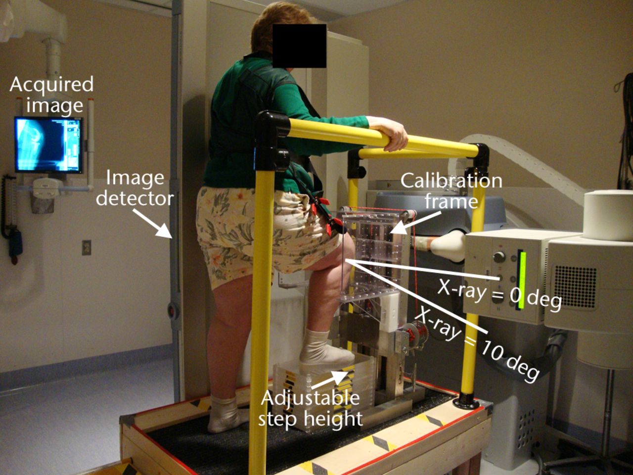
Fig. 1
Photograph showing the setup for sagittal imaging, with the subject standing on a platform with the right leg flexed and weightbearing and the right knee surrounded by a calibration frame. The flat panel image detector slides inside the vertical bed automatically with the X-ray source as it moves to acquire the biplane images in succession.
The subject’s knee is imaged at nominal 0°, 15°, 30°, 45°, 60°, 75°, 90°, and maximum flexion by adjusting the step height using different numbers of Plexiglas fitted increments, each with a thickness of 19 mm (0.75 inches). The required number of steps for each flexion angle (measured using a goniometer) is determined prior to imaging.
During imaging the subject’s knee is surrounded by a custom-designed calibration frame with known distributions of 1 mm tantalum beads (Fig. 2). It is necessary to calibrate every image since the X-ray source and detector move with each acquisition. The back face has a star pattern of 97 beads; a small plate in the middle has a rectangular grid pattern of 31 beads. For each knee flexion angle the calibration frame is moved up or down such that the smaller plate is aligned in front of the patella (Figs 1 and 2).
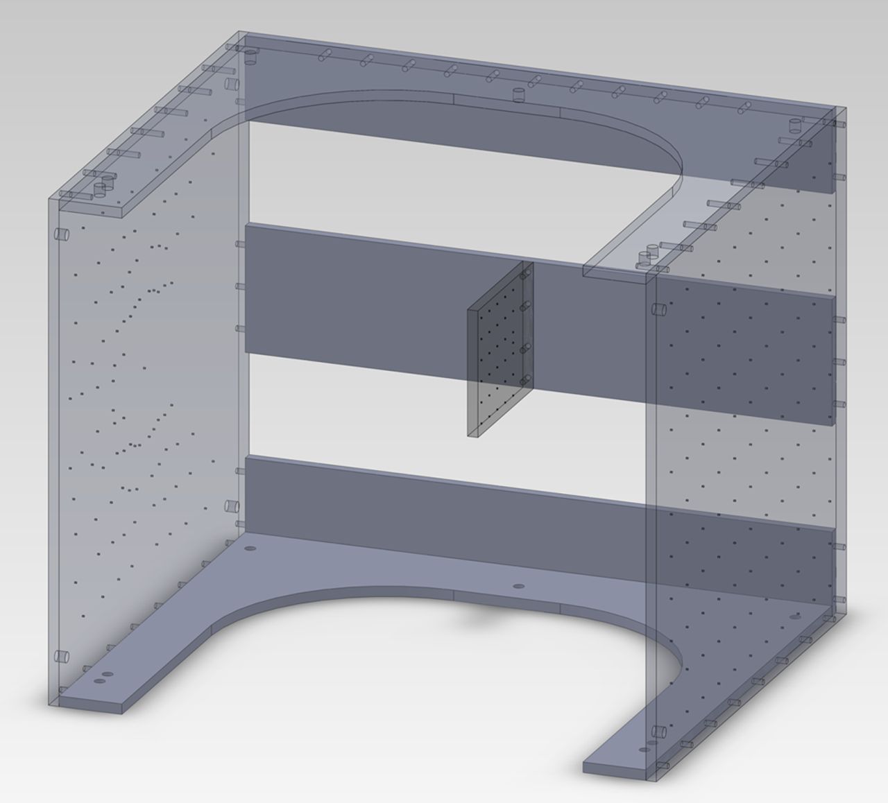
Fig. 2
Diagram showing the calibration frame used during imaging. The small square panel in the middle is positioned anterior to the subject’s patella.
The subject is instructed to put weight on the imaged or front leg by raising the back heel as if they are just about to stand up onto the step. The subject holds this position stationary using the handrail for stability while the system acquires two images, first with the X-ray source 10° below horizontal and second with the X-ray source directly horizontal, i.e. pure sagittal (Fig. 1). The transition between these two X-ray positions is electronically controlled and typically takes less than three seconds. The 10° difference was selected such that the knee remains in the field of view without readjustment of the detector position, which would increase the acquisition time. Imaging is performed from maximum knee flexion to full extension so that the subject proceeds from the most difficult position to the easiest.
Image calibration
Custom Matlab (The MathWorks Inc., Natick, Massachusetts) software was written to obtain the external and internal X-ray camera parameters. This is done by selecting the 2D bead locations in the image and comparing these positions with the known 3D coordinates derived from a CT scan of the calibration frame, using a modified Direct Linear Transform (DLT) approach.21 In order to verify the camera calibration, error residuals were computed using a bundle and triangulation approach.22
Obtaining 3D knee geometry
For the pre-operative knees we use high-resolution volumetric CT imaging (slice thickness: 0.6 mm; slice increment: 0.4 mm; in-plane resolution: 0.35 mm × 0.35 mm). In addition to the images of the knee joint, images are also acquired at the hip and ankle joints so that the femur and tibia mechanical axes can be defined.23 For the post-operative knees, the implants of the same kind as those in the subjects were obtained from the manufacturer and reverse-engineered using CT imaging.
Pre- and post-operative CT images are processed in a visualisation and analysis software package (ZIBAmira; ZIB, Berlin, Germany). The pre-operative CT images are autosegmented using statistical shape models developed at the Zuse Institute Berlin, similar to those described for the pelvis,24 with minor manual corrections required for osteophytes on the bone. The positions of the single prostheses in the post-operative knees are reconstructed from their respective CT images by aligning the reverse-engineered implants to the image data.25
Prosthesis coordinate systems are assigned to their 3D computer models using design features on each prosthesis component (Fig. 3). For the femoral prosthesis, the mediolateral (ML) axis is chosen as the line joining the centres of the tips of the pegs, the anteroposterior (AP) axis as the vector perpendicular to the plane bisecting the two pegs, and the proximodistal (PD) axis as the cross-product of the ML and AP axes. For the tibial prosthesis, the ML axis is taken as the line joining the notches on the sides of the tibial tray, the AP axis as the line parallel to the surface of the tibial tray, and the PD axis as the cross-product of the ML and AP axes. For the patellar prosthesis, the AP axis is computed as the axis of the articulating conical surface, the PD axis as the bisector of two fixations, and the ML axis as the cross-product of the PD and AP axes.
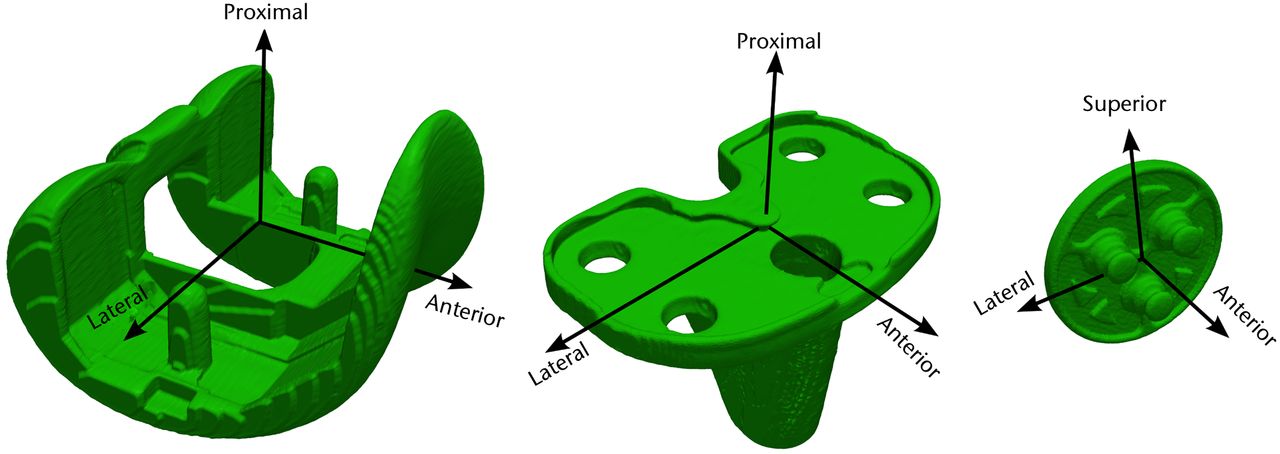
Fig. 3
Diagrams showing the coordinate systems for the femoral (left), tibial (centre), and patellar (right) prostheses, for use in the post-operative knees.
Coordinate systems are computed for each 3D bone model using anatomical features as described in Grood and Suntay23 (Fig. 4). For the femur, spheres are fit to the medial and lateral condyles, with the line joining the centres forming the ML axis.26 The origin of the femur is chosen as the mid-point of the ML line. The AP axis of the femur is computed as the cross-product of the ML axis and the femur origin to hip centre axis. Lastly, the femoral PD axis is the cross-product of the ML and AP axes. Similarly, for the tibia, the ML axis is defined as the line joining the centres of the medial and lateral tibial plateaus.27 The tibial origin is taken as the centre of the intercondylar eminence. The AP axis is computed as the cross-product of the ML axis and the tibia centre to ankle centre axis. And the PD axis is the cross-product of the ML and AP axes. For the patellar bone, the perpendicular to the anterior surface is considered as the AP axis. The ML axis is computed as the cross-product of the vector joining the geometric centre and the inferior pole, and the AP axis. The PD axis is obtained by taking the cross-product of the ML and AP axes.
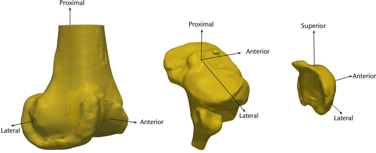
Fig. 4
Diagrams showing the coordinate system for the femur (left), tibia (centre), and patella (right), for use in the pre-operative knees.
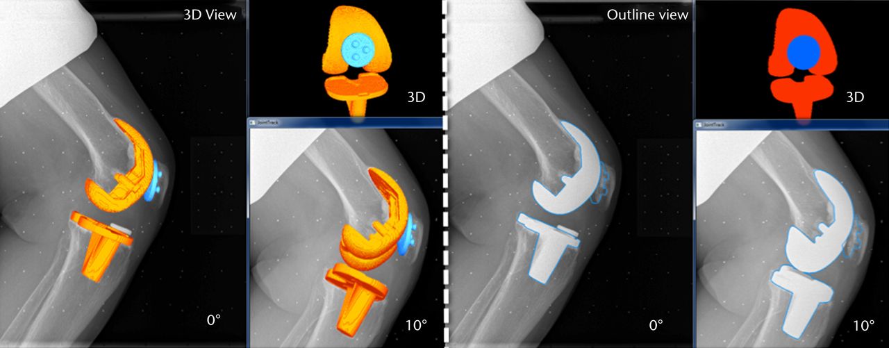
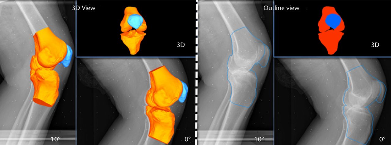
Figs. 5a - 5b
Images generated from the JointTrack Biplane software in three-dimensional (3D) view and silhouette view for a) the post-operative and b) the pre-operative knees.
Performing 2D-3D matching
The matching of the 3D bone or implant computer models to the 2D calibrated images is done using the JointTrack Biplane software (University of Florida, Gainesville, Florida). This open-source software rotates and translates the 3D model, automatically or with user input, until the silhouette provides an optimal fit to the 2D image, whether pre- or post-operative (Fig. 5).28 Due to the potential of slight subject movements between the two acquisitions, matching is done two times; first, one image is chosen as the primary and the other image as the secondary, and vice versa. Within the software, the 3D geometries’ silhouettes were matched to the primary image making use of both the images. The result is computed as the mean of the two matching procedures. It was found during pilot testing that the averaged results produced better repeatability than taking either matching on its own. The six DOF of PF tracking and TF kinematics are computed from the transformations of the patella and tibia bone or prosthesis coordinate systems relative to the femur bone or prosthesis coordinate system respectively.
Shift of the patellar bone or prosthesis apex is computed relative to the deepest point within the femoral groove. This is measured on the 3D reconstructions from the sagittal images.
Validation procedure
In order to validate the PF and TF measures, femoral, tibial and patellar prostheses were implanted into an artificial knee bone model using bone cement. The knee model with the prostheses was then fixed at a flexion angle of approximately 30°. This fixed knee model was imaged with CT and using our sequential biplane radiological protocol. The 3D prosthesis computer models were matched automatically to the CT data using a rigid-body version of the active shape modeling process, which is based on image gradients and known geometry.24 PF and TF pose from the sequential biplane images were compared with the pose from the CT scan for accuracy.
Repeatability analysis
In order to examine the interobserver repeatability of the procedure, two observers (SKS, SM) each determined the TF and PF kinematics for two different subjects, with differing patellar prosthesis visibilities, at eight different angles of flexion. One observer (SKS) repeated the procedure twice for two subjects in order to determine the intra-observer repeatability.
Results
The mean results for the six DOF PF tracking and TF kinematics of the six subjects are shown in Figures 6 and 7, respectively. Figure 8 shows the mean patellar shift with respect to the femoral groove. The pre-operative patellae were observed to have a greater external spin compared with the patellar prostheses in the post-operative knees, and to be more laterally located with respect to the femur at greater knee flexion. The change in the patellar and patellar prosthesis spin through knee flexion was less than 5.8° and 3.2°, respectively. The tibia in the pre-operative knees was more varus (adducted) and internally rotated compared with the tibial prosthesis in the post-operative knees.
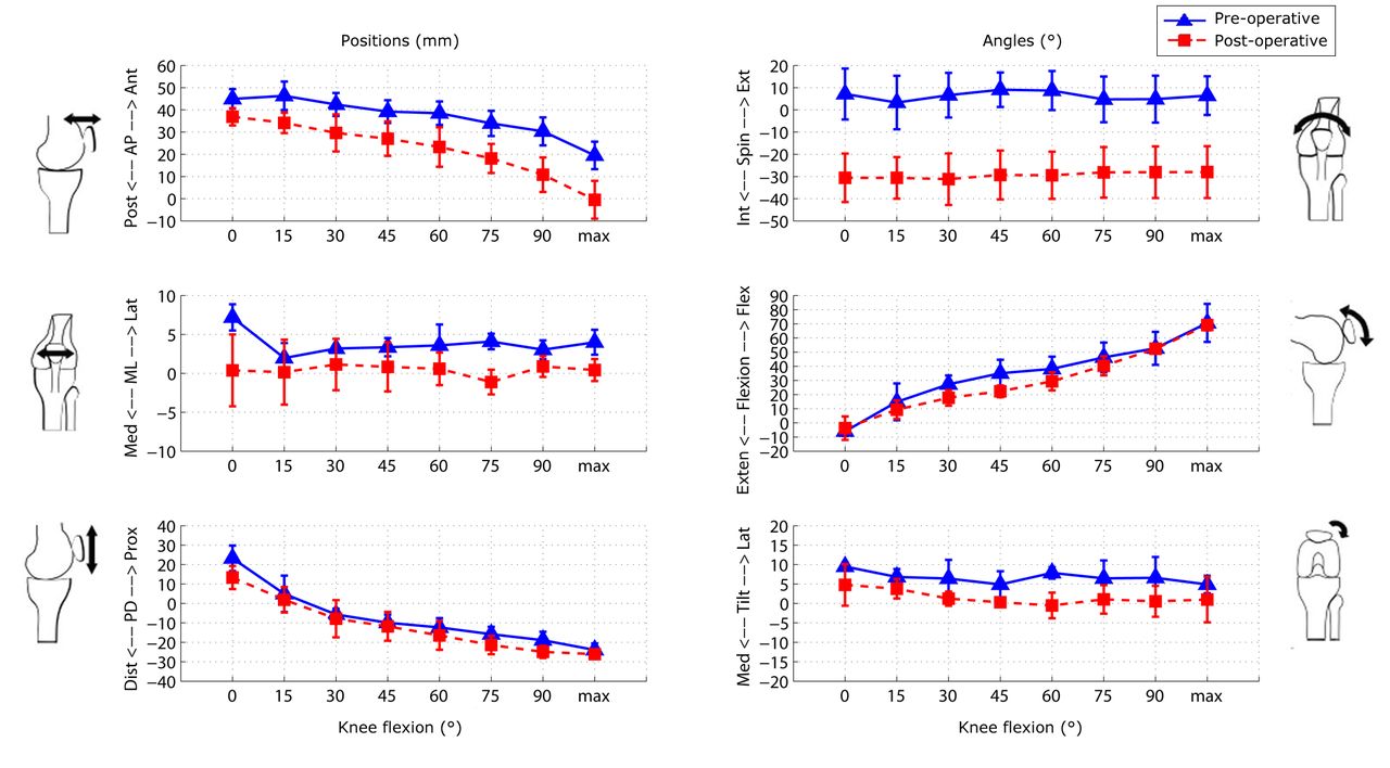
Fig. 6
Graphs showing the mean results for the six degrees of freedom patellofemoral tracking in the pre- and post-operative knees. The error bars denote the standard deviation (AP, anteroposterior; ML, mediolateral; PD, proximodistal; Int, internal; Ext, external; Exten, extension; Flex, flexion; Med, medial; Lat, lateral).
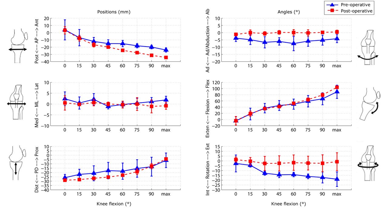
Fig. 7
Graphs showing the mean results for the six degrees of freedom tibiofemoral tracking in the pre- and post-operative knees. The error bars denote the standard deviation (AP, anteroposterior; ML, mediolateral; PD, proximodistal; Int, internal; Ext, external; Exten, extension; Flex, flexion; Med, medial; Lat, lateral).
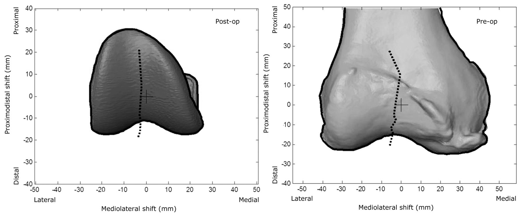
Fig. 8
Diagrams showing the mean patellar prosthesis/bone shift relative to the femoral groove centre, overlaid on an individual subject’s femoral prosthesis/femur. The black cross is the origin of the femoral prosthesis/femur and the black dotted line is the tracking of the patella as the knee flexes.
From validation testing, the mean absolute differences in the pose from CT imaging and the sequential biplane radiological protocol were less than 0.37 mm, 0.58° for PF and less than 0.84 mm, 0.50° for TF (Table I). Altogether, therefore, the mean accuracy was less than 0.9 mm and 0.6°.
Table I
Accuracy of sequential biplane radiological patellofemoral and tibiofemoral pose in comparison with CT pose
| Patellofemoral | Tibiofemoral | ||||||||||||||
|---|---|---|---|---|---|---|---|---|---|---|---|---|---|---|---|
| Translation* (mm) | Rotation† (°) | Translation* (mm) | Rotation‡ (°) | ||||||||||||
| Ant/ Pos | Sup/ Inf | Lat/ Med | Ext/ Int spin | Med/ Lat tilt | Exten/ Flx | Ant/ Pos | Sup/ Inf | Lat/ Med | Var/ Val | Int/ Ext | Exten/ Flx | ||||
| Radiology | 33.35 | -6.02 | 2.70 | 3.93 | 3.35 | -16.94 | -20.37 | -25.39 | -2.64 | -1.95 | 16.02 | -35.60 | |||
| CT | 33.72 | -6.11 | 2.83 | 4.34 | 2.77 | -16.06 | -20.37 | -26.13 | -1.80 | -2.34 | 16.52 | -35.53 | |||
| Absolute difference | 0.37 | 0.09 | 0.13 | 0.41 | 0.58 | 0.88 | 0.00 | 0.74 | 0.84 | 0.39 | 0.50 | 0.07 | |||
-
* Ant, anterior; Pos, posterior; Sup, superior; Inf, inferior; Lat, lateral; Med, medial † Ext, external; Int, internal; Exten, extension; Flx, flexion ‡ Var, varus; Val, valgus
The mean interobserver differences for the repeatability analysis were < 1 mm for TF and PF translation except for mediolateral translation (TF, 1.8 mm; PF, 1.2 mm). Mean TF rotational differences were less than 1° and mean PF rotational differences were less than 2° except for patellar mediolateral tilt (2.8°). Intra-observer differences were similar (Table II).
Table II
Inter- and intra-observer repeatability of sequential biplane radiological procedure (mean with standard deviation)
| Patellofemoral | Tibiofemoral | ||||||||||||||
|---|---|---|---|---|---|---|---|---|---|---|---|---|---|---|---|
| Translation* (mm) | Rotation† (°) | Translation* (mm) | Rotation‡ (°) | ||||||||||||
| Ant/ Pos | Sup/ Inf | Lat/ Med | Ext/ Int spin | Med/ Lat tilt | Exten/ Flx | Ant/ Pos | Sup/ Inf | Lat/ Med | Var/ Val | Int/ Ext | Exten/ Flx | ||||
| Inter-observer | 0.49 (0.32) | 0.45 (0.26) | 1.20 (1.10) | 1.87 (1.21) | 2.77 (1.86) | 2.01 (1.41) | 0.25 (0.13) | 0.26 (0.24) | 1.85 (1.68) | 0.43 (0.33) | 0.60 (0.60) | 0.67 (0.41) | |||
| Intra-observer | 0.20 (0.15) | 0.51 (0.45) | 1.85 (1.41) | 1.28 (0.52) | 1.67 (1.34) | 1.98 (0.71) | 0.26 (0.39) | 0.4 (0.25) | 2.44 (2.21) | 0.44 (0.46) | 0.67 (0.46) | 0.47 (0.31) | |||
-
* Ant, anterior; Pos, posterior; Sup, superior; Inf, inferior; Lat, lateral; Med, medial † Ext, external; Int, internal; Exten, extension; Flx, flexion ‡ Var, varus; Val, valgus
The camera calibration error residuals from using the modified-DLT method were verified using the bundle and triangulation approach and found to be < 2 pixels, where 1 pixel length equals 0.145 mm.
The mean radiation dose was 438 µGy.m2 (sd 114) for the procedure, resulting in an effective dose of 0.04 mSv (sd 0.02). The effective radiation dose from the CT scanning was approximately 2.5 mSv. The combined radiation dose of approximately 2.54 mSv (sd 0.02) is less than the yearly background radiation level of approximately 3 mSv and much less than 7 mSv reported for an average chest CT.29
Discussion
A novel in vivo radiological imaging protocol for measuring six DOF of PF tracking and TF kinematics was successfully developed and validated. Current biplane fluoroscopy systems are highly sophisticated. However, their cost limits their availability and accessibility. Furthermore, positioning of two X-ray sources and detectors in order to measure PF tracking after TKR can be a challenge as the patella is only visible within an angle of approximately 20° from sagittal plane; at greater angles the large femoral metal component obscures the view. Adapting an electronically-controlled X-ray source and a flat-panel detector with a calibration frame in the image permits quick acquisitions of the knee from two different perspectives, thereby providing better repeatability (TF: 0.25 mm to 2.44 mm and 0.43° to 0.67°; PF: 0.2 mm to 1.85 mm and 1.28° to 2.77°) than a single-plane fluoroscopy system (theoretical TF and PF for the natural knee: 0.21 mm to 5.6 mm and 0.35° to 1.3°)10 and less than that of a biplane fluoroscopy system (PF pre-operative only: 0.04 mm to 0.11 mm and 0.22° to 0.38°).13
Our procedure can be adapted to work with most C-arm or X-ray systems commonly available in a clinical setting. This sequential biplane imaging approach permits investigations that were not previously possible. The study has been executed using three pre-operative and three post-operative subjects. This shows sufficient feasibility for the application of the protocol for in vivo imaging. Further volunteer recruitment is underway in order to study differences in PF tracking and TF kinematics between pre- and post-TKR knees as well as between different prosthesis types, with a focus on gender-specific versus traditional components.
Validation and repeatability analysis were performed for the post-TKR knees, as the main aim of this study was to measure PF tracking and TF kinematics after the procedure. In validation testing the knee prostheses were fixed in artificial bone at only one angle of 30°, as at this angle the patellar prosthesis is known to engage in the femoral groove.30,31 Our accuracy (TF: 0.84 mm, 0.5°; PF: 0.37 mm, 0.88°) was better than single-plane fluoroscopy systems (TF: 0.5 mm (in-plane), 6.6 mm (out-of-plane), 1.1°)32 and approaching dynamic biplane systems (PF: 0.395 mm, 0.88°).13
To our knowledge, this is the first time that six DOF in vivo PF tracking has been reported for post-TKR knees through a full range of movement. The sequential nature of the acquisitions limits the method to static poses, however a recent report has described comparable knee kinematics between static and dynamic squatting tasks.33
Due to the sequential nature of capturing the biplane images, some subject movement is expected. Our approach of matching the 3D bone or prosthesis computer models two times, with each image alternately serving as the primary matched image, and then averaging the two results to obtain the kinematics, reduced the errors and improved the accuracy. The angle between the sequential images was kept at 10° in order to keep the acquisition time to a minimum. However, the low separation of the two X-ray positions may be lowering the accuracy. The angle between the X-ray positions could be widened by taking more time between the acquisitions to reposition the detector so that the X-ray source can be moved further. This requires that the subject hold the static position for longer, but could be valuable for better depth information.
The protocol is reasonably demanding due to being weightbearing at a variety of flexion angles. Although all six subjects were able to complete the protocol, they reported that it did take some effort. This may have introduced a bias in terms of who chooses to volunteer, such as healthier, more mobile patients. This is acceptable for matched-pair studies, but a more streamlined procedure may be appropriate for subjects with greater mobility or pain issues.
There are several potential ways to streamline the protocol, if desired, to reduce image acquisition or analysis time. First, CT imaging is not essential, although we have found it useful, especially since each subject is unique and each imaging modality provides additional information; CT allows the acquisition of the hip-knee-ankle angle and internal/external prosthesis rotation measurements. Post-operatively, seeing the 3D positions of the implants, especially the patellar prosthesis, aids in determining the 2D-3D matching, especially to know the 3D placement of the patellar pegs. As an alternative, it may be possible in the pre-operative case to fit statistical shape models to the 2D images, particularly with the biplane information. Secondly, depending on the research question, fewer angles of flexion could be acquired.
TKR is a common procedure with a dramatically increasing number of surgeries performed each year.34 Our procedure provides a tool to measure complete PF tracking and TF kinematics accurately in pre- and post-TKR individuals. This method can help identify why some individuals continue to experience problems after TKR. It can also allow us to track changes over time. Outcomes of this research could help improve prosthesis design, surgical technique, and patient selection.
The authors would like to thank Kirsteen Robbie and Kyla MacLachlan for the biplane image acquisitions and helping in the fine-tuning of the protocol; Roy Pooley and his staff for acquiring the CT scans; Dr. S. Banks and Dr. S. Mu for support with JointTrack Biplane and the modified DLT calibration code; Dr. R. Frayne, Dr. J. Ronsky, Dr. C. Hutchison and Dr. D. Wilson for their technical and clinical advice; and Dr. B. Frizzell and Dr. L. Hahn for their radiological input.
1 Baker PN , van der MeulenJH, LewseyJ, GreggPJ. The role of pain and function in determining patient satisfaction after total knee replacement: data from the National Joint Registry for England and Wales. J Bone Joint Surg [Br]2007;89-B:893–900. Google Scholar
2 Katchburian MV , BullAM, ShihYF, HeatleyFW, AmisAA. Measurement of patellar tracking: assessment and analysis of the literature. Clin Orthop Relat Res2003;412:241–259.CrossrefPubMed Google Scholar
3 Banks SA , HodgeWA. 2003 Hap Paul Award Paper of the International Society for Technology in Arthroplasty: design and activity dependence of kinematics in fixed and mobile-bearing knee arthroplasties. J Arthroplasty2004;19:809–816. Google Scholar
4 Baldini A , AndersonJA, Cerulli-MarianiP, et al.Patellofemoral evaluation after total knee arthroplasty: validation of a new weight-bearing axial radiographic view. J Bone Joint Surg [Am]2007;89-A:1810–1817. Google Scholar
5 Stiehl JB , KomistekRD, DennisDA, KeblishPA. Kinematics of the patellofemoral joint in total knee arthroplasty. J Arthroplasty2001;16:706–714.CrossrefPubMed Google Scholar
6 Lin F , MakhsousM, ChangAH, HendrixRW, ZhangLQ. In vivo and noninvasive six degrees of freedom patellar tracking during voluntary knee movement. Clin Biomech (Bristol, Avon)2003;18:401–409.CrossrefPubMed Google Scholar
7 Shih YF , BullAM, McGregorAH, AmisAA. Active patellar tracking measurement: a novel device using ultrasound. Am J Sports Med2004;32:1209–1217.CrossrefPubMed Google Scholar
8 Sharma A , LeszkoF, KomistekRD, et al.In vivo patellofemoral forces in high flexion total knee arthroplasty. J Biomech2008;41:642–648.CrossrefPubMed Google Scholar
9 Leszko F , SharmaA, KomistekRD, et al.Comparison of in vivo patellofemoral kinematics for subjects having high-flexion total knee arthroplasty implant with patients having normal knees. J Arthroplasty2010;25:398–404.CrossrefPubMed Google Scholar
10 Fregly BJ , RahmanHA, BanksSA. Theoretical accuracy of model-based shape matching for measuring natural knee kinematics with single-plane fluoroscopy. J Biomech Eng2005;127:692–699.CrossrefPubMed Google Scholar
11 Song CY , LinJJ, JanMH, LinYF. The role of patellar alignment and tracking in vivo: the potential mechanism of patellofemoral pain syndrome. Phys Ther Sport2011;12:140–147.CrossrefPubMed Google Scholar
12 Fernandez JW , AkbarshahiM, KimHJ, PandyMG. Integrating modelling, motion capture and x-ray fluoroscopy to investigate patellofemoral function during dynamic activity. Comput Methods Biomech Biomed Engin2008;11:41–53.CrossrefPubMed Google Scholar
13 Bey MJ , KlineSK, TashmanS, ZauelR. Accuracy of biplane x-ray imaging combined with model-based tracking for measuring in-vivo patellofemoral joint motion. J Orthop Surg Res2008;3:38.CrossrefPubMed Google Scholar
14 Amiri S , WilsonDR, MasriBA, SharmaG, AnglinC. A novel multi-planar radiography method for three dimensional pose reconstruction of the patellofemoral and tibiofemoral joints after arthroplasty. J Biomech2011;44:1757–1764.CrossrefPubMed Google Scholar
15 Anglin C , HoKC, BriardJL, et al.In vivo patellar kinematics during total knee arthroplasty. Comput Aided Surg2008;13:377–391.CrossrefPubMed Google Scholar
16 Sawaguchi N , MajimaT, IshigakiT, et al.Mobile-bearing total knee arthroplasty improves patellar tracking and patellofemoral contact stress: in vivo measurements in the same patients. J Arthroplasty2010;25:920–925.CrossrefPubMed Google Scholar
17 Carpenter RD , BrilhaultJ, MajumdarS, RiesMD. Magnetic resonance imaging of in vivo patellofemoral kinematics after total knee arthroplasty. Knee2009;16:332–336.CrossrefPubMed Google Scholar
18 Moro-oka T , MatsudaS, MiuraH, et al.Patellar tracking and patellofemoral geometry in deep knee flexion. Clin Orthop Relat Res2002;394:161–168.CrossrefPubMed Google Scholar
19 Connolly KD , RonskyJL, WestoverLM, KupperJC, FrayneR. Differences in patellofemoral contact mechanics associated with patellofemoral pain syndrome. J Biomech2009;42:2802–2807.CrossrefPubMed Google Scholar
20 Fitzgerald SJ , TrousdaleRT. Why knees fail in 2011: patient, surgeon, or device?Orthopedics2011;34:513–515. Google Scholar
21 Hatze H . High-precision three-dimensional photogrammetric calibration and object space reconstruction using a modified DLT-approach. J Biomech1988;21:533–538.CrossrefPubMed Google Scholar
22 Lichti DD , ChapmanMA. Constrained FEM self-calibration. Photogrammetric Engineering and Remote Sensing1997;63:1111–1119. Google Scholar
23 Grood ES , SuntayWJ. A joint coordinate system for the clinical description of three-dimensional motions: application to the knee. J Biomech Eng1983;105:136–144.CrossrefPubMed Google Scholar
24 Seim H, Kainmueller D, Heller M, et al. Automatic segmentation of the pelvic bones from CT data based on a statistical shape model. In: Botha CP, Kindlmann G, Niessen WJ, Preim B, eds. Eurographics Workshop on Visual Computing for Biomedicine. 2008. http://www.zib.de/lamecker/publications/vcbm2008.pdf (date last accessed 15 August 2012). Google Scholar
25 Ho KC , SaevarssonSK, RammH, et al.Computed tomography analysis of knee pose and geometry before and after total knee arthroplasty. J Biomech2012;45:2215–2221.CrossrefPubMed Google Scholar
26 Iranpour F , MericanAM, DandachliW, AmisAA, CobbJP. The geometry of the trochlear groove. Clin Orthop Relat Res2010;468:782–788.CrossrefPubMed Google Scholar
27 Cobb JP , DixonH, DandachliW, IranpourF. The anatomical tibial axis: reliable rotational orientation in knee replacement. J Bone Joint Surg [Br]2008;90-B:1032–1038.CrossrefPubMed Google Scholar
28 Acker S , LiR, MurrayH, et al.Accuracy of single-plane fluoroscopy in determining relative position and orientation of total knee replacement components. J Biomech2011;44:784–787.CrossrefPubMed Google Scholar
29 Mettler FA , HudaW, YoshizumiTT, MaheshM. Effective doses in radiology and diagnostic nuclear medicine: a catalog. Radiology2008;248:254–263.CrossrefPubMed Google Scholar
30 Pedowitz RA, Chung CB, Resnick D. Magnetic resonance imaging in orthopedic sports medicine. New York: Springer, 2008. Google Scholar
31 Varadarajan KM , FreibergAA, GillTJ, RubashHE, LiG. Relationship between three-dimensional geometry of the trochlear groove and in vivo patellar tracking during weight-bearing knee flexion. J Biomech Eng2010;132:061008.CrossrefPubMed Google Scholar
32 Banks SA , HodgeWA. Accurate measurement of three-dimensional knee replacement kinematics using single-plane fluoroscopy. IEEE Trans Biomed Eng1996;43:638–649.CrossrefPubMed Google Scholar
33 Mu S , Moro-OkaT, JohalP, et al.Comparison of static and dynamic knee kinematics during squatting. Clin Biomech (Bristol, Avon)2011;26:106–108.CrossrefPubMed Google Scholar
34 DeFrances CJ , CullenKA, KozakLJ. National Hospital Discharge Survey: 2005 annual summary with detailed diagnosis and procedure data. Vital Health Stat 132007;165:1–209.PubMed Google Scholar
Funding statement:
This work was supported by the Natural Sciences and Engineering Research Council of Canada, Canadian Institutes for Health Research, Alberta Innovates – Technology Futures, and the University of Calgary.
Author contributions:
G. B. Sharma: Study design, Protocol development, Hardware design, Software design, Data acquisition, Data analysis
S. K. Saevarsson: Protocol development, Data acquisition, Data analysis
S. Amiri: Study design, Protocol development
S. Montgomery: Data acquisition, Data analysis
H. Ramm: Data analysis
D. D. Lichti: Study design, Data analysis
R. Lieck: Data analysis
S. Zachow: Technical resources, Supervision at Zuse Institute
C. Anglin: Study design, Protocol development, Data acquisition, Resources, Supervision
ICMJE Conflict of Interest:
The authors have no other conflicts of interest. The study sponsors had no involvement in the study or manuscript preparation.
©2012 British Editorial Society of Bone and Joint Surgery. This is an open-access article distributed under the terms of the Creative Commons Attributions licence, which permits unrestricted use, distribution, and reproduction in any medium, but not for commercial gain, provided the original author and source are credited.
